
Published: 22 May 2026
Reading Time: 8 minutes
Reviewer: Simon Scrapes, Founder
You know that sinking feeling when a finished board looks fine, but then one bad joint kills the whole run? It happens fast. A tiny profile mistake, too much heat, or uneven paste can turn a solid build into scrap.
If you’re trying to learn how to use reflow oven settings the right way, you’re not alone. The reflow machine process looks simple from the outside. Paste, place, heat, done. But real results come from control, repeatable setup, and knowing what each stage is doing to your PCB.
This guide walks through the SMT reflow oven process in plain English. We’ll cover setup, temperature stages, reflow oven cycle time calculation, common defects, and PCB best practices, including tips for reflow oven double sided PCB work and careful notes on reflow soldering at home. If you’re running an EMS line or just trying to understand how to reflow a circuit board in an oven without wrecking it, this will help.
Reviewed for practical manufacturing accuracy and process clarity. This article is intended for engineers, buyers, operators, and teams comparing real SMT production workflows in 2026.
Why the reflow process matters so much
A reflow profile is not just a heating step. It shapes solder joint quality, component safety, and long-term board reliability. Strong SMT work depends on controlled heating and cooling so the solder paste melts, wets properly, and then solidifies without stress.
When teams master the smt reflow oven process, they usually see fewer solder bridges, fewer cold joints, and more stable output. Research on high-quality PCB assembly also points to better consistency and longer product life when reflow stages are controlled well, especially for fine-pitch and lead-free builds in this SMT reflow overview.
Here’s the simple version:
- Good reflow helps parts bond well
- Bad reflow creates weak or failed joints
- Repeatable profiles save time and rework
- Tight control matters even more with dense modern PCBs
And yes, this impacts cost. A lot. One profile issue across a production batch can waste hours.
What the reflow machine process looks like
At a basic level, the reflow machine process follows a clear path:
- Apply solder paste to the PCB
- Place components on the paste
- Move the board through the oven on a conveyor
- Heat the board in stages
- Cool it at a controlled rate
- Inspect the finished assembly
That sounds easy enough. But each step affects the next one.
If the stencil print is uneven, the oven cannot fix it. If components shift during placement, the profile will not rescue bad alignment. Reflow works best when the whole line is stable, from paste storage to post-reflow inspection.
For larger EMS or OEM teams, this is where equipment choice matters. A precision oven with stable zone control, conveyor consistency, and repeatable thermal behavior can make day-to-day production far less chaotic. That’s one reason companies look at suppliers like Sun and Mountain SMT when they need scalable SMT equipment that fits a growing production line.
Expert Tip: Before changing your oven recipe, check the upstream print and placement steps first. A lot of “reflow problems” actually start before the board enters the oven.
How to use reflow oven settings step by step
Let’s keep this practical. If you’re asking how to use reflow oven controls in a real setting, start here.
1. Check the solder paste data sheet
Your paste tells you the target temperature range, ramp rate, time above liquidus, and cooling guidance. Start there, always. If you skip this part, you’re basically guessing with heat.
Some teams still hunt for a reflow soldering process pdf to use as a generic template. That can help as a learning tool, sure, but a profile should match your actual paste, board mass, and component mix.
2. Confirm PCB and component limits
Not every part likes the same heat exposure. Connectors, plastic bodies, LEDs, and tall components may have tighter limits than the solder itself. Read those specs before you run a profile.
3. Set the oven zones
Most ovens split heating into multiple zones. Each zone supports one part of the process, like preheat or peak reflow. The exact numbers depend on your materials, but the pattern stays pretty consistent.
4. Match conveyor speed to heat exposure
This is where reflow oven cycle time calculation comes in. The board needs enough time in each zone, but not too much. Faster conveyor speed shortens total exposure. Slower speed increases soak and time above liquidus.
5. Run a test board with thermocouples
Don’t trust settings just because they worked last month. Board thickness, copper weight, and component density can shift thermal behavior. A profiled test board gives you real data.
6. Inspect, adjust, repeat
No one nails every profile on the first pass. Not usually. Check for bridges, tombstoning, dull joints, voids, and skewed parts, then tune the profile carefully.
The 4 main stages in the SMT reflow oven process
Most boards move through four core thermal stages. Different articles split them into four or five steps, but this model is the easiest to use on the floor.
| Stage | What happens | Why it matters |
|—|—|—|
| Preheat | Board warms gradually | Reduces thermal shock and starts flux activation |
| Soak | Temperature evens out across the PCB | Helps activate flux and reduce temperature spread |
| Reflow | Solder reaches melt point and forms joints | Creates the electrical and mechanical bond |
| Cooling | Board cools in a controlled way | Helps joint strength and lowers defect risk |
Preheat
This first part raises temperature at a controlled rate. Too fast, and components or the board can get stressed. Too slow, and you can dry out the paste too early.
Soak
The soak stage gives the assembly time to even out. This is helpful on boards with mixed thermal mass, like when one area has a chunky connector and another has tiny passive parts.
Reflow peak
This is the hot zone. The solder goes liquid, wets the pads and leads, and forms the joint. If the peak is too low, joints may be weak. If it’s too high, parts can warp or get damaged.
Cooling
Cooling matters more than people think. A controlled drop helps the solder solidify with good grain structure and lower stress. Rush this part and defects can creep in.
How to calculate reflow oven cycle time
This part confuses a lot of people at first. Fair enough.
A simple way to think about reflow oven cycle time calculation is this:
Cycle time depends on heated tunnel length, conveyor speed, and the time the board must spend in each thermal stage.
A basic estimate looks like this:
Cycle time = total heated length / conveyor speed
For example:
- Heated length: 3.6 meters
- Conveyor speed: 0.6 meters per minute
- Estimated heating travel time: 6 minutes
Then add loading, exit, and handling realities from your actual line.
But here’s the thing, a useful cycle time is not just about total travel. You also need enough time above liquidus for the solder paste you use. So the real process target mixes oven length, zone temperatures, and belt speed.
If you’re running production in 2026, profile software and logged thermal data make this much easier. Good ovens often include better controls and data tracking, which can help production teams cut guesswork and reduce repeat faults.
Expert Tip: If you speed up the conveyor to raise throughput, recheck peak temperature and soak balance right away. More boards per hour means nothing if your yield drops.
PCB best practices before and during reflow
A lot of reflow quality comes from what happens before the oven.
Keep solder paste under control
Use fresh paste, store it correctly, and let it return to room temperature before printing if the supplier says to. Old or poorly handled paste can lead to slump, weak wetting, or extra voiding.
Print with consistency
Stencil thickness, aperture design, and printer setup all matter. Uneven deposits often lead to bridging or starved joints. The oven can’t magically fix that. I wish it could. It can’t.
Place accurately
Component alignment affects self-centering during reflow, but only within reason. If placement is way off, melted solder may pull the part into a bad position or create a short.
Watch board support
Thin boards can sag when heated. Good support rails or center support help avoid warping, especially on larger panels.
Validate with inspection
AOI and, when needed, X-ray help close the loop between setup and output. Teams that inspect, log defects, and tune based on real findings tend to improve faster, as explained in this plain-language guide to reflow soldering process control.
Special note on reflow oven double sided PCB work
Double-sided boards add a twist. Sometimes two twists.
With reflow oven double sided PCB assembly, one side is usually reflowed first, then the second side is processed after more paste and placement. The question most people ask is simple: will the first side fall off during the second pass?
Usually, no, if the process is designed correctly. Surface tension in the molten solder can hold many smaller components in place during the second reflow. But component size, board orientation, and profile control all matter.
Best practices include:
- Put larger or heavier parts on the top side when possible
- Reflow the more complex side first if process flow allows
- Use glue only in special cases, not as the default answer
- Validate the second-pass profile carefully
- Watch for shadowing and uneven heat on dense builds
If you’re planning frequent double-sided work at scale, stable conveyor handling and repeatable zone control become a big deal. That’s where production-grade ovens from specialist SMT equipment makers, including Sun and Mountain SMT, can fit better than entry-level systems.
Can you reflow PCB in oven at home?
Short answer: people do it, but you need to be careful.
Searches for reflow soldering at home and how to reflow a circuit board in an oven are common because hobby builders want a cheap path to SMT assembly. And for simple prototypes, toaster oven conversions and small desktop units can work.
But there are real limits:
- Household ovens are not food-safe after soldering use
- Temperature control may be uneven
- Fumes and ventilation need attention
- Lead-free paste still needs profile control
- Sensitive parts can get damaged fast
If you’re a hobby user, use a dedicated unit for electronics only, profile it as well as you can, and don’t treat kitchen gear like a production tool. If you’re an EMS or OEM team, skip the improvised setup and use equipment built for repeatability.
Common reflow defects and what usually causes them
Here is a quick troubleshooting table you can keep handy.
| Defect | Common cause | What to check first |
|—|—|—|
| Solder bridges | Too much paste, poor placement, high slump | Stencil design and print quality |
| Cold joints | Low peak temp or short time above liquidus | Profile and paste spec |
| Tombstoning | Uneven wetting forces, unbalanced heating | Pad design, paste volume, ramp |
| Voiding | Flux outgassing, poor soak, pad design | Paste, profile, thermal balance |
| Component skew | Misplacement or uneven solder pull | Pick-and-place accuracy |
| Burned flux residue | Too much heat or too much time | Peak zone settings and conveyor speed |
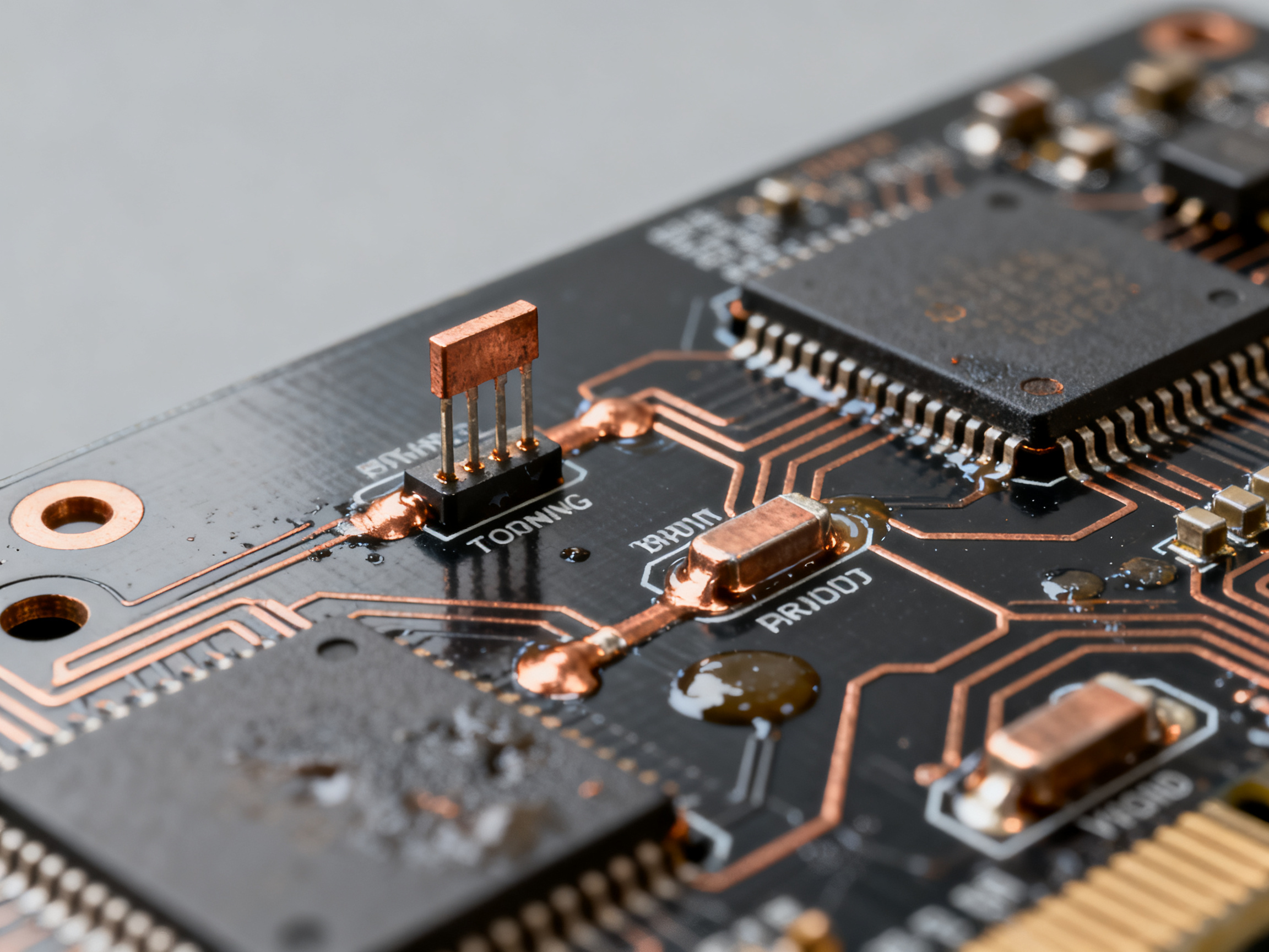
Funny enough, a lot of defects repeat for boring reasons. Same paste issue. Same stencil wear. Same rushed profile tweak from a Friday afternoon shift.
A simple roadmap to get better at how to reflow
If you want to move from “I kind of get it” to “we can run this reliably,” focus on these steps:
- Learn the four reflow stages well
- Read paste and component specs every time
- Profile real boards, not just empty test coupons
- Tie defects back to root causes
- Standardize machine recipes and inspection checks
- Track yields and rework trends over time
- Train operators and engineers on the same process language
That roadmap lines up with broader SMT process guidance from industry sources that stress profiling, defect analysis, inspection feedback, and standards-based control across modern reflow workflows.
Expert Tip: Save your known-good profiles by board family, paste type, and component mix. That small habit can save hours the next time a repeat job lands on your line.
Final thoughts
The best answer to how to use reflow oven settings is not one magic temperature chart. It’s a repeatable process. Start with paste data, confirm component limits, profile the board, inspect the result, and keep tuning until the output is stable.
Whether you’re learning the smt reflow oven process for prototypes or managing full production, the goal stays the same: strong joints, low defects, and predictable throughput. And if your current equipment keeps making that harder than it should be, it may be time to look at a more stable oven setup that fits your line and volume.
If you’re comparing reflow systems for 2026 production, or you want a better fit for EMS and OEM scaling, Sun and Mountain SMT is worth a look for precision ovens and connected line equipment built around repeatability, uptime, and practical factory use.
Trusted SMT results come from disciplined setup, careful profiling, and real inspection feedback. Teams that treat reflow as a controlled process, not just a hot tunnel, tend to build better boards, waste less time, and solve defects faster.