
Published: 21 June 2026
Reading Time: 11 minutes
Reviewer: Simon Scrapes, Founder
You know that moment when material has to move fast, cleanly, and without making a mess of the whole factory floor? That’s where pneumatic conveyor systems start to make a lot of sense. In busy plants, especially in electronics manufacturing, even a small delay in moving powders or dry bulk materials can slow the next step, add cleanup work, or create quality problems that nobody wants to chase later.
A pneumatic conveyor system uses air or gas to move dry material through an enclosed pipeline. Simple idea. Big payoff. Because the material stays inside the line, teams usually get better dust control, less product loss, and a smoother flow between machines. That’s a big reason these systems show up in food, pharma, chemicals, plastics, and electronics production, where clean handling matters a lot (AMG Engineering on pneumatic conveying basics).
Jace Liu is a seasoned manufacturing systems engineer specializing in automation processes for electronics production lines. With over 15 years of experience in manufacturing innovation, Jace has helped EMS and OEM companies globally to enhance efficiency and integrate advanced equipment smoothly into their workflows.
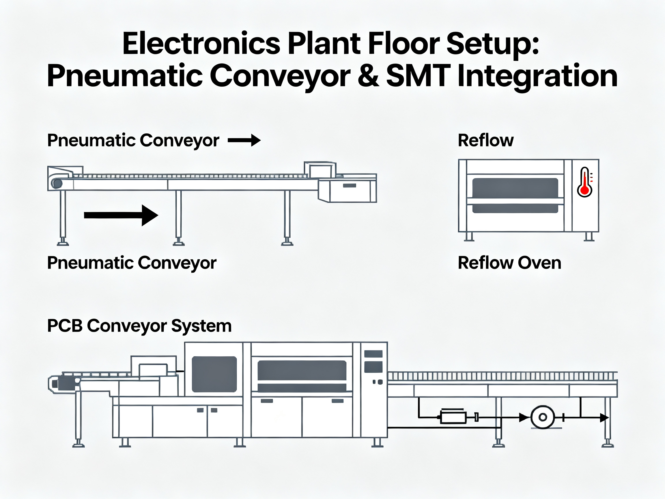
For electronics manufacturers, this isn’t just about moving powder from point A to point B. It’s about keeping production steady. It’s about cutting manual handling. And it’s about protecting sensitive materials while supporting automated lines. If you’re already working with SMT equipment, reflow ovens, or PCB conveyor systems, pneumatic handling can fit into that bigger picture pretty naturally. Companies like Sun and Mountain SMT focus on line efficiency and equipment integration, so this kind of system often becomes part of a wider automation plan.
In this guide, we’ll walk through how pneumatic conveyors work, where they fit best, and what to watch for if you’re planning a new setup in 2026. If you’re trying to reduce downtime and make your manufacturing flow less clunky, you’re in the right place.
How Pneumatic Conveyors Work: Principles, Components, and Mechanisms
At first glance, it seems almost too simple. Air moves product through a pipe. Done, right? Well, sort of. The real answer is a bit more interesting, because good pneumatic conveyor systems depend on balance, pressure, material behavior, and a few core parts all working together.
The main parts that make the system run
Most pneumatic conveyor systems include four key pieces:
| Component | What it does | Why it matters |
| — | — | — |
| Air mover | Creates the airflow or pressure difference | Gives the system the force to move material |
| Pipeline | Carries the material from one point to another | Shapes speed, routing, and system efficiency |
| Feeding device | Adds material into the air stream at a controlled rate | Helps stop clogging, surging, or waste |
| Separation unit | Removes material from the air at the end of the line | Lets product collect safely and air vent or recirculate |
The air mover is usually a blower, fan, or vacuum source. This is the engine of the whole setup. It creates either positive pressure, which pushes material forward, or negative pressure, which pulls it through the line. Both can work well. It really depends on the plant layout, the material itself, and how clean or contained the process needs to be.
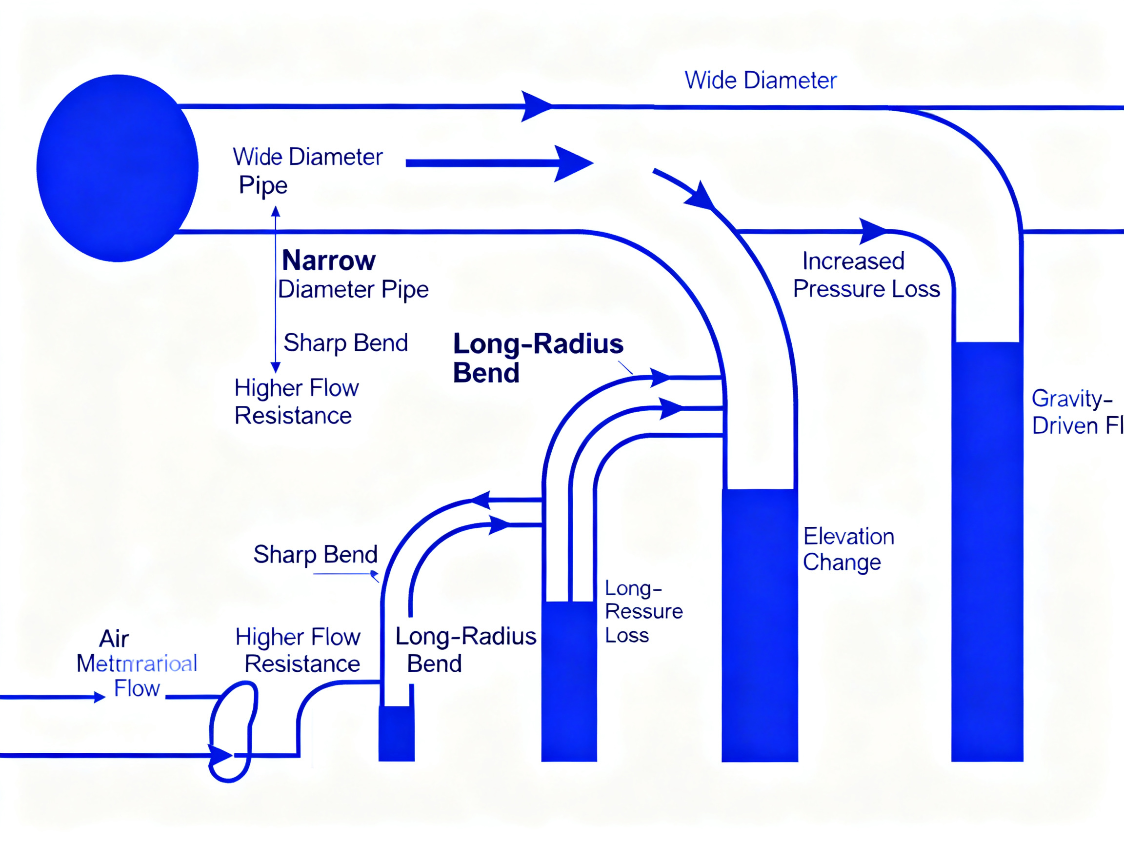
The pipeline is more than just tubing on a wall. Pipe diameter, bend radius, run length, and vertical lift all change how the material flows. A tight bend might save floor space, but it can also increase wear, slow movement, or break fragile product. In electronics settings, where powders can be fine and sensitive, those details matter a lot.
Then comes the feeding device. This part meters product into the system at a pace the air stream can actually handle. Rotary valves, screw feeders, and venturi-style inlets are common choices. If feeding is too fast, the line can plug. If it’s too slow, the system may waste energy. That’s the annoying middle ground nobody wants.
Finally, the separation unit captures the product at the destination. Cyclones, filters, and receivers are common here. They separate the material from the carrying air, so the product drops into a hopper, bin, or process machine while the air moves on. Clean discharge matters, especially if the conveyor links with SMT lines, powder dosing stations, or other automated tools from suppliers like Sun and Mountain SMT.
Expert Tip: In electronics manufacturing, small component changes can have a big impact. Matching the feeder, pipe diameter, and receiver size to the material flow rate often cuts dust, product breakage, and line stoppages before they start.
What actually moves the material
So, how pneumatic conveyors work in real life? The short version is this: air velocity lifts or suspends material particles, then carries them through a closed line. But the exact motion depends on the system type, material size, density, shape, and moisture level.
Some materials move in a more suspended, almost cloud-like way. Others travel in plugs or slower pockets. That’s why two systems that look similar on paper can behave very differently on the shop floor. Fine resin powder is not going to act like plastic pellets. And neither will behave quite like a blended solder-related dry material used in electronics processing.
Airflow dynamics matter here. Velocity has to stay high enough to keep the material moving, but not so high that it shreds product, wears out elbows, or drives up power use. Pressure also has to stay within a range the system can support from start to finish. If one section of line creates too much resistance, the whole setup can get moody fast.
A good way to think about it is like traffic. When the road is open and speeds are steady, cars keep moving. But when too many cars enter too quickly, or one lane narrows without warning, everything backs up. Pneumatic conveying is kind of the same. Air is the road. Material is the traffic.
Why many plants choose this over traditional transport
Compared with bucket elevators, screw conveyors, or open belt systems, pneumatic conveyor systems usually offer cleaner transport and more layout freedom. Since material stays enclosed, plants often see less dust in the air and lower contamination risk. That’s a big deal for regulated spaces and for electronics plants trying to keep nearby equipment clean.
They also tend to fit awkward layouts better. Need to route material around columns, above work cells, or across a ceiling line? Pipes can usually do that more easily than bulky mechanical conveyors. That’s one reason these systems are still gaining attention across processing industries in 2026, especially where space is tight and cleanliness matters (IQS Directory explains common pneumatic conveyor uses and benefits).
That said, traditional transport still has its place. Mechanical conveyors can be better for some heavy, abrasive, or oddly shaped materials, and they may use less energy in certain cases. So this is not a one-size-fits-all answer. But if your priority is enclosed handling, flexible routing, and better integration with automated production lines, pneumatic conveying often wins.
And that’s really the point. You’re not just picking a way to move material. You’re picking how smoothly the whole line works together.