
Published: 08 October 2026
Reading Time: 18 minutes
Reviewer: Simon Scrapes, Founder
Introduction: Setting the Stage for Modern Electronics Assembly
Think about the smartphone in your pocket. Now think about how that tiny device holds thousands of electrical connections, all perfectly formed and working together. Ever wonder how those connections get made? The answer sits in a process called reflow soldering, and it runs almost everything electronic you own.
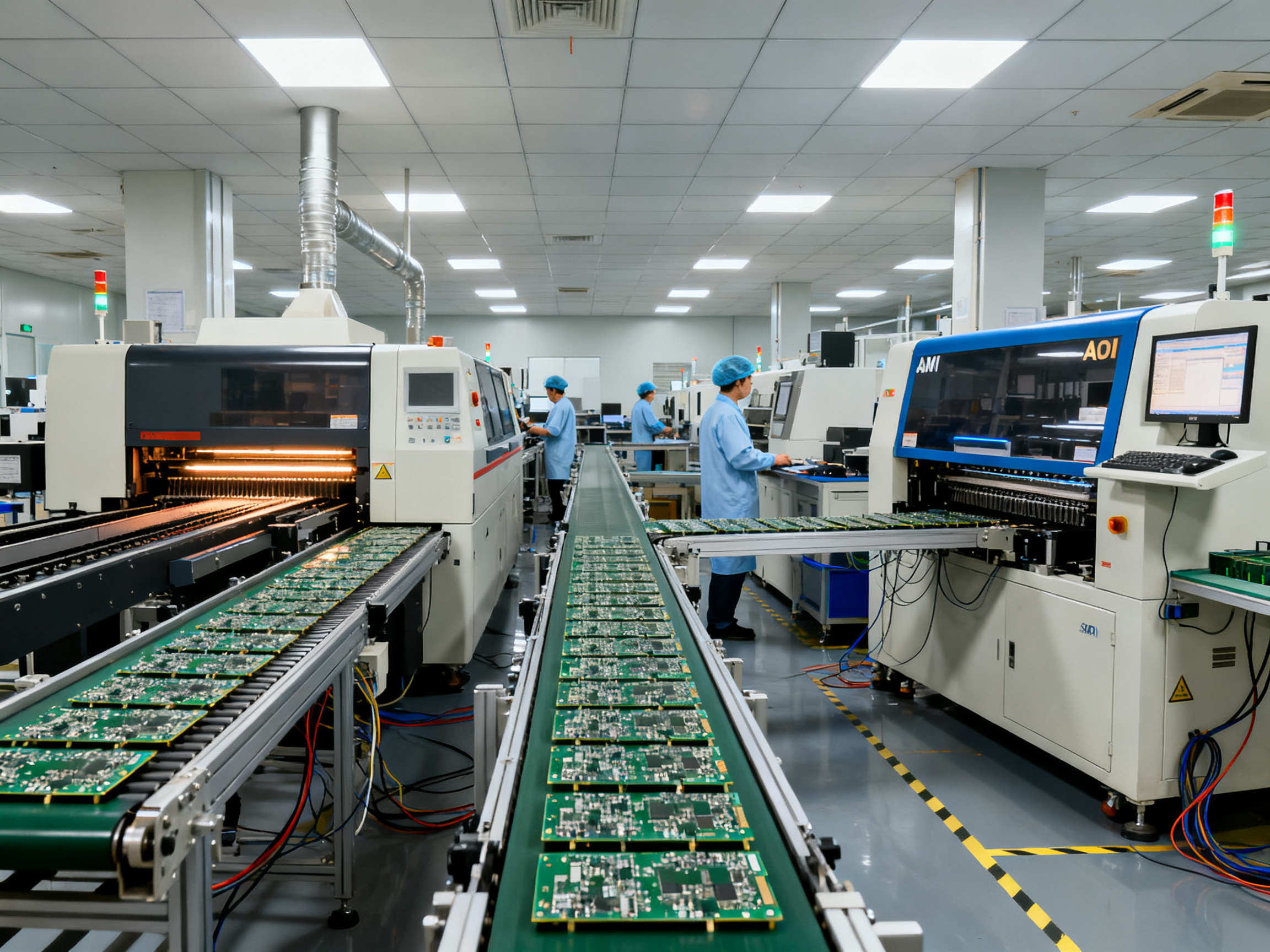
Reflow soldering is a heat-based process that melts solder paste to create permanent electrical connections between components and circuit boards. The solder paste gets applied to metal pads on the board, components get placed on top, and then the whole assembly moves through a reflow oven where controlled heating melts the solder into solid joints. Once cooled, you have working connections that hold up under daily use.
This process sits at the heart of surface mount technology (SMT) assembly, which is how most electronics get built today. According to Mordor Intelligence, reflow soldering held 46.57% of the solder materials market in 2025 and remains the standard method for consumer electronics, server hardware, and telecommunications equipment 1. The SMT market itself was valued at $6.11 billion in 2025 and is projected to reach $6.66 billion in 2026, driven by IoT device production and electric vehicle electronics 3.
So why does this matter to you? If you’re specifying equipment, running production lines, or managing supply chains, the reflow solder process directly impacts your product reliability, manufacturing costs, and throughput. We have seen firsthand how getting the reflow temperature profile right separates high-yield production runs from costly rework headaches.
This guide covers everything you need to know about reflow soldering. We will walk through the four stages of the reflow process, break down how to build and optimize temperature profiles for lead-free solders, explore your equipment options and how to choose between them, and then dig into the most common defects and how to fix them. Whether you are a production engineer fine-tuning a profile, a procurement specialist evaluating reflow oven investments, or a supply chain manager ensuring your contract manufacturers meet quality standards, there is something here for you.
Let us get started.
[Author placeholder] – This article provides foundational knowledge for production engineers, procurement specialists, and supply chain managers involved in electronics manufacturing equipment decisions. For personalized guidance on reflow soldering equipment for your specific production requirements, contact Sun and Mountain SMT’s technical team.## What Is Reflow Soldering? Core Concepts and Fundamentals
The reflow solder process sits at the heart of how your electronics get built. It is a surface mount technology process where tiny metal particles suspended in a sticky chemical mixture get melted together to create permanent bonds between components and circuit boards.
Think of solder paste like toothpaste. You squeeze it out onto specific spots on the board through a stencil, then place components on top. Those components stay put because the paste is sticky. But sticky does not equal permanent. The assembly has to go through the reflow oven where controlled heat melts the paste into solid metal joints.
Here is where it gets interesting. Solder paste is not just melted metal. It contains tiny solder spheres, usually made from tin, silver, and copper (called SAC305 in industry speak), suspended in a chemical flux. The flux does several jobs: it cleans oxide off metal surfaces, prevents oxidation during heating, and helps the molten solder flow where it needs to go. Once the oven cools everything down, the flux residue stays behind, and you have solid electrical connections.
So how does this differ from other ways of joining electronics? Let me break it down.
Reflow soldering vs. wave soldering
Wave soldering was the standard before surface mount took over. Picture a waterfall of molten solder that boards pass through face-down. Components get inserted into holes and the solder waves up through the holes to make connections. This works great for through-hole parts, but surface mount components? They need something gentler. Reflow applies heat more evenly from above and below, which matters when you have tiny components sitting on top of the board instead of pushed through it.
Reflow soldering vs. hand soldering
Hand soldering is exactly what it sounds like. A technician holds a soldering iron and touches each joint individually. This works for prototypes, repairs, and small runs. But for high-volume production where you need thousands of identical connections per board? Human hands just cannot match the speed and consistency of an SMT reflow oven. One misplaced component or cold joint can cause an entire batch to fail.
The reflow process also allows for components underneath other components (like that smartphone chip stacked on memory). Try doing that with wave soldering. Not happening.
Modern reflow ovens heat boards through multiple zones with precise temperature control. The conveyor moves boards through these zones following a specific thermal profile. Get that profile wrong and you end up with cold joints, bridges between pins, or components that tombstone (stand up on end because one side soldered before the other).
Pro Insight: The reflow solder process depends heavily on the interaction between your solder paste specification, component thermal limits, and oven capabilities. These three things must be balanced together, not treated as separate decisions.
Understanding these fundamentals helps when you are debugging assembly problems or specifying equipment for your line. The process sounds simple on paper, but every detail matters when you are running production volume.
For most SMT assembly in 2026, reflow is the default choice. It handles fine-pitch components, supports automation, and produces consistent results across high volumes. Your smartphone, laptop, car electronics, and probably your coffee maker all went through a reflow oven during manufacturing.## What Is Reflow Soldering Used For? Applications and Industry Use Cases
Reflow soldering shows up everywhere electronics exist. The process powers everything from the device in your hand to the systems keeping cars safe on the road. Here is where you will find reflow ovens doing their thing.
Consumer Electronics Manufacturing
This is the biggest user of reflow soldering. Smartphones, tablets, laptops, smartwatches, and wireless earbuds all rely on SMT reflow assembly. These products pack thousands of components into tiny spaces, and reflow handles that density better than any other method.
Consumer electronics prioritize two things: cost and speed. Manufacturers run high volumes through reflow ovens at maximum throughput while keeping defect rates extremely low. A single smartphone board might have 50+ individual solder joints, and each one has to work right the first time.
The trend toward smaller, thinner devices keeps pushing manufacturers toward tighter reflow temperature profiles and better process control. Your latest phone probably has components stacked on top of each other, which requires precise thermal management during reflow.
Automotive Electronics
Car electronics have exploded in recent years. Modern vehicles contain dozens of control units, sensors, infotainment systems, and increasingly, electric vehicle power electronics. Over 58% of EV power management systems and control boards get assembled using SMT lines, according to industry estimates.
Automotive reflow demands more than consumer-grade processes. These boards have to work reliably for years in harsh conditions. Temperature cycling, vibration, and humidity all test solder joints. That is why automotive manufacturers often specify tighter profile controls, better atmosphere management during reflow, and stronger documentation of process parameters.
Electric vehicles push this further. Battery management systems, power converters, and charging circuits handle high currents, which means solder joint quality directly affects safety and reliability. Many automotive shops now use nitrogen reflow or even vapor phase systems for their most critical assemblies.
Industrial, Medical, Aerospace, and Telecom
Beyond consumer and automotive, reflow soldering serves demanding sectors.
Medical devices need documented process control and traceability. A pacemaker or imaging equipment failure is not an option, so medical manufacturers treat reflow profiling as a critical quality activity.
Aerospace and defense take this even further. Military specifications require extraordinary process control, inspection, and documentation. Every reflow profile might need logging, approval, and traceability back to the assembly records.
Telecommunications equipment, industrial controllers, and power supplies all fall into this high-reliability category. These applications balance cost against field reliability, often favoring robust process control over pure speed.
| Industry Sector | Primary Reflow Priority | Typical Requirements |
|—|—|—|
| Consumer Electronics | Speed, cost, high volume | IPC Class 2, fast changeovers |
| Automotive / EV | Long-term reliability, safety | IPC Class 3, documentation, nitrogen |
| Industrial | Durability, uptime | IPC Class 2-3, consistent profiles |
| Medical | Traceability, patient safety | Documentation, validated processes |
| Aerospace / Defense | Mission reliability | MIL-SPEC requirements, extreme control |
| Telecommunications | Density, availability | Fine-pitch capability, void control |
Why Industry Matters for Your Decisions
Understanding these applications helps when you are specifying equipment or evaluating contract manufacturers. A shop running mainly consumer products will optimize for speed and changeover time. A shop building automotive electronics will emphasize profile repeatability and documentation systems.
Your reflow oven choice should match your target market. High-volume consumer work needs throughput and automation. High-reliability work needs process control and traceability. Knowing the difference saves you from buying the wrong equipment or working with the wrong manufacturer.
Sun and Mountain SMT builds reflow ovens for both scenarios, with options ranging from high-throughput systems for consumer assembly to precision-controlled units for automotive and aerospace applications.## The Four Stages of the Reflow Soldering Process
Every board that goes through a reflow oven follows the same basic journey. The SMT reflow oven splits this journey into four distinct zones, each with its own job to do. Understanding these zones helps you troubleshoot problems and optimize your reflow temperature profile for better results.
Stage 1: The Preheat Zone
The preheat zone gets things started. The board enters at room temperature and the oven gradually raises its temperature, usually at about 1 to 3 degrees Celsius per second. This slow climb serves two purposes.
First, it drives off the solvents trapped in the solder paste. Solder paste contains liquid chemicals that keep it workable, and these need to evaporate before things get really hot. Rush this step and the solvents boil suddenly, creating solder balls that scatter across your board.
Second, preheat prevents thermal shock. Components on your board have different thermal masses. A tiny resistor heats up fast while a large connector takes longer. Slam everything with instant heat and the thermal stress cracks components or causes uneven wetting. The preheat zone gives everything time to warm up together.
Typical preheat targets a board temperature between 150 and 200 degrees Celsius, though your specific paste datasheet will tell you the exact window.
Stage 2: The Thermal Soak Zone
After preheat comes the thermal soak zone, sometimes called the activation zone. Here the board sits at a steady intermediate temperature, usually around 150 to 200 degrees Celsius. This stage does a couple of critical things.
The flux really gets going here. Flux is the chemical cleaner in solder paste that removes oxide from metal surfaces. It activates more fully in this temperature range, preparing surfaces for the bonding to come. Any leftover solvents from the paste finish evaporating quietly rather than causing chaos later.
The soak also equalizes temperature across the board. Smaller components heat faster than larger ones. The soak gives everything time to catch up so the whole board is at roughly the same temperature before moving to the hot zone. Typical soak times run about 60 to 90 seconds, but your paste manufacturer will specify the exact recommendation.
Stage 3: The Reflow Zone
Now things get serious. The reflow zone shoots the temperature above the solder melting point. For lead-free SAC305 solder, that means hitting around 235 to 250 degrees Celsius. The solder melts and flows, forming the actual metallurgical bonds between component leads and pads.
The flux finishes its work, the cleaned metal surfaces get wet by molten solder, and capillary action pulls solder up into the connection points. Time above liquidus matters here. This is how long the solder stays molten, and most profiles target 30 to 90 seconds above 217 degrees Celsius for SAC alloys.
Too little time above liquidus means cold joints that do not wet properly. Too much time risks damaging components or creating too thick an intermetallic layer. We always watch this number on our thermal profiler.
Stage 4: The Cooling Zone
The final zone brings temperatures back down. Controlled cooling solidifies the solder joints with proper grain structure. Cooling too fast stresses the board and can crack connections. Cooling too slow makes the grain structure coarser and weaker.
Most profiles run cooling at about 2 to 4 degrees Celsius per second. This rate gives clean solidification without thermal shock. Once the board drops below the solder solidus, it exits the oven ready for inspection and the next step in production.
Pro Insight: Critical temperature ramp rates and why they matter for different component types. Uneven heating between components with mismatched thermal masses can cause tombstoning, where small components stand up on end because one side reaches reflow temperature before the other. Varying conveyor speeds and zone temperatures help balance these differences across production runs.
Mastering these four zones separates smooth production runs from defect-filled headaches. Each stage sets up the next one, and skipping steps or rushing through them creates problems that show up later in testing or, worse, in the field.## Understanding the Reflow Temperature Profile
Every solder joint your board makes goes through a carefully choreographed dance with heat. The reflow temperature profile is the choreographer’s notes, a precise map showing exactly what temperature the board reaches and when, throughout its journey through the oven.
Think of it like a recipe. The recipe does not just say “add heat.” It tells you exactly what temperature to hold, for how long, and when to start cooling down. Get the recipe wrong and your soufflé collapses. Get the reflow profile wrong and your solder joints do the same thing, more or less.
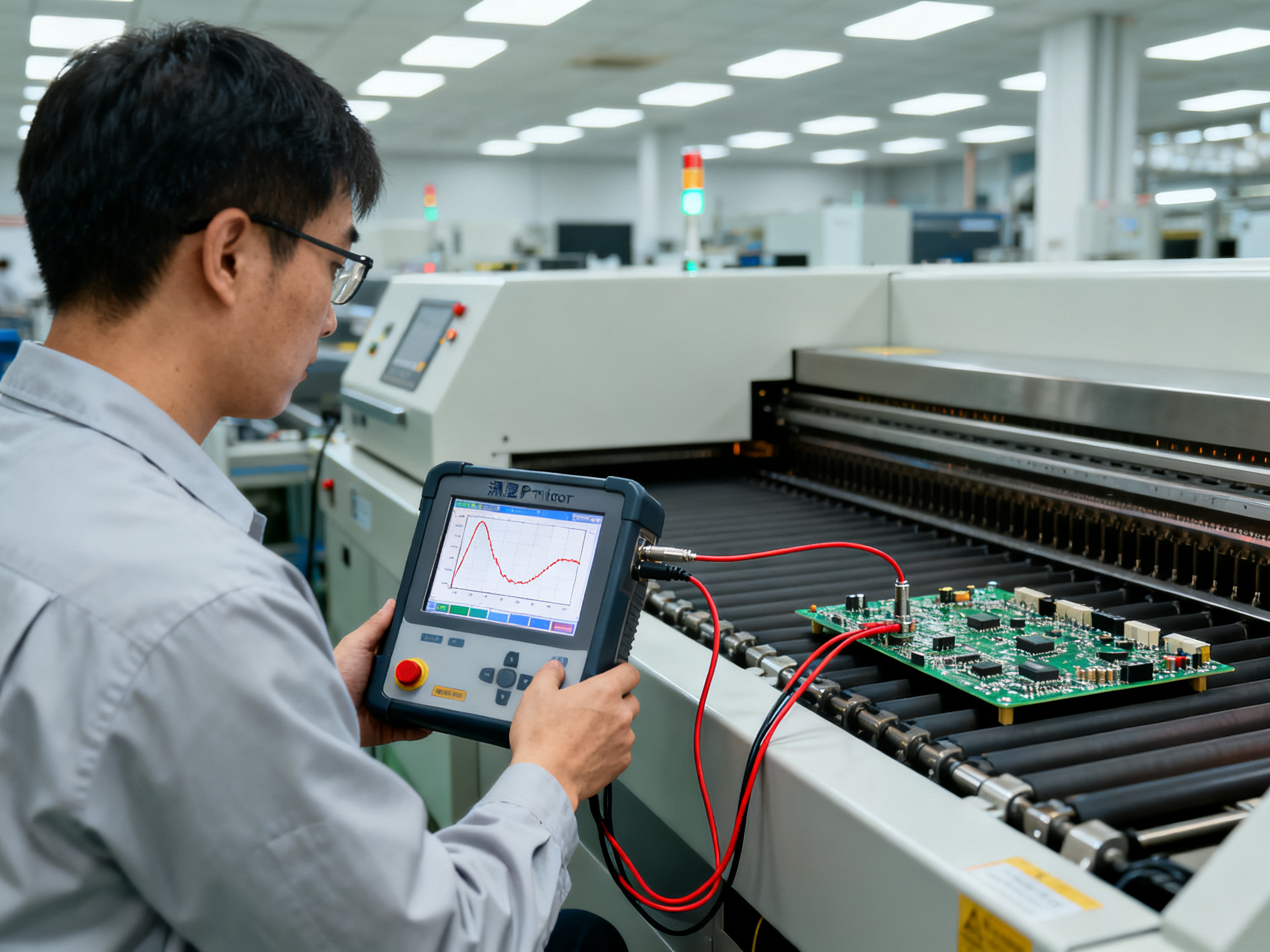
The profile gets plotted as a graph with time on the horizontal axis and temperature on the vertical axis. As your board travels through the oven on the conveyor, thermocouples attached to the board capture temperature readings at multiple points. Those readings build the curve you see in profiling software, showing preheat at the start, a soak plateau in the middle, a peak during reflow, and cooling at the end.
We always run a profiler before committing to production. You connect small thermocouples to representative spots on a test board, run it through the oven empty of components, and watch what happens. This tells you whether your settings actually produce the thermal environment you think they do.
Key Profile Parameters to Watch
Several numbers define whether your reflow profile works or fails.
Ramp Rate tells you how fast temperature climbs during preheat, measured in degrees Celsius per second. Most profiles target 1 to 3 degrees per second for the initial climb. Too fast and you risk thermal shock cracking components. Too slow and you waste time and expose the board to unnecessary heat dwell.
Soak Time or thermal soak duration matters because it lets the board temperature equalize across all components. A large connector and a tiny resistor heat up at different rates. The soak gives them a chance to reach similar temperatures before things get serious. Typical soak times run 60 to 90 seconds in the 150 to 200 degree range for lead-free SAC305 solder.
Time Above Liquidus (TAL) counts how long the solder stays molten. This is critical. Too little time means the solder does not flow properly and creates cold joints. Too much time degrades the intermetallic layer and risks damaging sensitive components. For SAC305, you want roughly 30 to 90 seconds above 217 degrees Celsius, though your paste datasheet specifies the exact window.
Peak Temperature is the maximum heat your board reaches. For lead-free SAC305, that typically lands between 235 and 250 degrees Celsius. The exact peak depends on your solder paste formulation and what your components can handle. We have seen profiles that pushed 260 degrees, but that is risky territory unless every single component on your board explicitly permits it.
Cooling Rate shapes the final grain structure of your solder joints. Too fast creates stress that cracks connections over time. Too slow makes the grain structure coarse and weak. Most profiles target 2 to 4 degrees per second during cooling.
Balancing Competing Requirements
Here is the tricky part. Your components have temperature limits, and your solder paste has temperature requirements, and those two things do not always line up perfectly.
A heat-sensitive semiconductor might max out at 240 degrees. Your paste datasheet recommends a 245 degree peak. You have five degrees of margin, probably not enough for production variation. So you need to decide: accept the risk, find a paste with a lower peak window, or reconsider the component choice.
This balancing act extends to all the profile parameters. High-mass boards need slower ramps and longer soaks. Fine-pitch components need careful attention to bridging risk. BGAs need void control, which means profile tuning around flux outgassing.
The goal is always the same: achieve complete, void-free wetting on every joint without exceeding any component limit. That sounds simple, but it means testing, measuring, and iterating until your process holds steady.
For high-mix production, you end up building a library of validated profiles, each tuned for board families with similar thermal mass and component sensitivity. Changing products means loading a different profile, which is why profile management and changeover discipline matter so much on the production floor.
Expert Tip: When evaluating reflow ovens for high-mix production environments, prioritize machines with independent zone control and rapid profile switching capability. The ability to store multiple recipes and transition between them without extended downtime directly impacts your effective throughput across product changeovers.
A good profile gives you reliable joints you can count on. A bad one gives you expensive rework bills and field failures that cost way more than the time spent getting the profile right the first time.## Reflow Soldering Equipment: Types and Selection Criteria
The reflow oven you choose shapes everything about your production line. It determines how fast you can run, what board sizes you can handle, and how consistent your solder joints stay across thousands of assemblies. Here is what you need to know about the main types available in 2026.
Forced Convection Reflow Ovens
These are the workhorses of SMT assembly. Forced convection ovens use fans to push hot air through multiple zones, creating even heating across your board regardless of component color or surface finish. The heated air wraps around components from all directions, so a dark-colored capacitor does not heat faster than a light-colored resistor sitting next to it.
Forced convection held 47.2% of the reflow soldering equipment market share in 2025, according to industry data 2. That dominance makes sense because these ovens handle most board types without drama. They scale well for high-volume lines, work naturally with modern lead-free profiles, and integrate easily with conveyor systems and upstream/downstream equipment.
The downside? Fans consume energy, and maintaining uniform airflow takes ongoing attention. You also need to factor in nitrogen costs if your process requires low-oxygen atmospheres, which adds roughly 10-15% to material costs 8.
Vapor Phase Reflow Systems
Vapor phase works differently. Instead of hot air, these systems use a boiling fluid that creates vapor. The vapor surrounds your board completely, condensing on cooler surfaces to transfer heat with remarkable uniformity. Think of it like steam heating your face in a bathroom, except the vapor condenses on your board instead of your skin.
The heating is incredibly even because vapor fills every gap and conforms to component shapes naturally. No shadowing, no hot spots, no component-color sensitivity. The process also excludes oxygen by design, which means better wetting and cleaner joints without spending money on nitrogen.
One production case study showed vapor phase reduced voiding on critical components from roughly 40% down to under 5% compared to traditional reflow, with claimed cost reductions around 20% 1. That kind of improvement matters for automotive electronics and power modules where void control affects thermal performance.
The catch is throughput. Vapor phase typically runs slower than inline convection, and you have fluid management complexity to deal with. These systems shine when thermal uniformity matters more than raw speed.
Infrared Reflow Systems
Infrared (IR) ovens heat components directly using electromagnetic radiation. No hot air, no fluid, just focused heat that certain materials absorb more readily than others. IR systems offer fast ramp rates and simpler machine construction, which appeals to shops with tight budgets or space constraints.
But here is the problem. Different components absorb IR energy at different rates. A black plastic connector heats faster than a shiny metal heatsink. Components also cast shadows, blocking heat from reaching parts behind them. This uneven absorption makes IR less predictable for mixed-technology boards with diverse component types.
IR reflow works for specialized applications like rework stations or single-product lines where you control the board mix tightly. For general SMT assembly with varied products and component types, the inconsistency issues usually outweigh the cost advantages.
Choosing the Right Equipment
Selecting a reflow oven comes down to matching capabilities to your actual production needs. Here are the factors that matter most.
Throughput requirements: How many boards per hour do you need to produce? Forced convection generally wins for pure speed and inline integration.
Board size and thermal mass: Large, heavy, or unevenly loaded boards benefit from vapor phase’s uniform heating. Standard consumer boards usually run fine on convection.
Temperature accuracy and repeatability: Your oven must hold the same profile across thousands of cycles. Independent zone control lets you fine-tune heating across different board geometries.
Oxygen control: Nitrogen atmospheres improve wetting and reduce oxidation but add cost. Vapor phase gives you oxygen-free processing without the nitrogen bill.
Energy efficiency: Modern ovens vary significantly in power consumption. Look beyond headline specs to actual kWh per panel data.
Maintenance and support: Factor in preventive maintenance schedules, spare parts availability, and vendor response time. Downtime costs more than any energy savings.
Total cost of ownership: Purchase price is just the start. Include energy, consumables, maintenance labor, and potential rework costs from defects when comparing options.
Expert Tip: When evaluating reflow ovens for high-mix production environments, prioritize machines with independent zone control and rapid profile switching capability. The ability to store multiple recipes and transition between them without extended downtime directly impacts your effective throughput across product changeovers. We have tested this firsthand on production lines running 15+ product variants daily. The time savings compound quickly.
Equipment Specification Checklist
Before signing any purchase agreement, confirm these specifications match your requirements:
| Specification | What to Verify |
|—|—|
| Maximum board size | Does your largest product fit with margin for handling? |
| Zone count | More zones mean finer temperature control for complex boards |
| Temperature range | Must cover your paste peak requirement plus margin |
| Conveyor speed range | Should match your target throughput and TAL requirements |
| Oxygen monitoring | Real-time O2 measurement per zone, not just gas flow |
| Profile storage | How many recipes can the system hold? |
| Energy consumption | Ask for measured kWh data, not just wattage ratings |
| Maintenance intervals | What needs servicing and how often? |
| Integration | Does it work with your existing MES and inspection systems? |
The right reflow oven for your operation depends on your specific product mix, volume requirements, and quality standards. Forced convection handles most applications well, vapor phase addresses the most demanding thermal challenges, and infrared serves specialized needs. Sun and Mountain SMT offers equipment across all three categories, with consultation available to match your requirements to the appropriate technology.
Common Reflow Soldering Defects and Their Root Causes
Even with the best equipment and perfectly tuned profiles, defects happen. The key is knowing what to look for and where to start digging when something goes wrong. Most reflow defects fall into a handful of categories, and each one has a handful of usual suspects behind it.
Tombstoning and Non-Wetting One End
Tombstoning is exactly what it sounds like. A small component stands up on end like a tombstone, with one solder joint formed properly and the other end pointing skyward. The technical name is Non-Wetting One End (NWO), and it happens when wetting forces get unbalanced during reflow.
Here is the deal. When solder melts on one side of a component before the other side, the liquid solder on the first side pulls that end down into the joint. If the other side has not melted yet, you get a tug-of-war, and one end wins by pulling the whole part upright.
Common causes include pad size mismatch (one pad is bigger so it holds more heat), uneven solder paste deposition (one aperture printed more than the other), and asymmetric copper planes connecting to the pads. If a pad ties into a large copper pour, that copper acts like a heatsink and delays melting on that side.
Placement accuracy matters too. If a component sits off-center, one set of pads gets more paste coverage than the other. We have seen tombstoning show up suddenly after a stencil wore out slightly, reducing paste transfer on just one side.
Bridging and Solder Balls
Bridging happens when solder connects two adjacent pads that should stay separate. This creates short circuits that usually kill board functionality right away.
The usual culprit is too much solder. Stencil apertures that are oversized, a stencil that is too thick, or paste that slumps after printing all deposit more metal than the joint needs. Surface tension during reflow pulls the excess between pads that happen to be close together.
Solder balls are little spheres of solder scattered around joints instead of staying where they were printed. They often come from moisture in the paste flashing to steam during heating. If the preheat ramp is too fast, that steam shoots solder particles away from the target area. Contaminated pads or oxidized solder powder also contribute to balling.
Both defects connect to the same root causes: paste volume control and thermal ramp management. Fix the printing process and the preheat zone, and bridging and balling usually disappear.
Cold Joints and Insufficient Solder
A cold joint looks dull and grainy instead of shiny and smooth. It did not wet properly, which means the connection is mechanically weak and may fail electrically over time.
The most common cause is insufficient heat. Either the peak temperature was too low, or the time above liquidus was too short. Both mean the solder stayed solid or only partially melted, so it never properly bonded to the metal surfaces.
Solder paste degradation causes problems too. If paste sat too long at room temperature, absorbed moisture, or exceeded its shelf life, the flux chemistry breaks down and can no longer clean surfaces effectively. Oxidized metal does not wet well, period.
Large thermal mass areas create cold joints by acting as heat sinks. A pad connected to a heavy copper plane may never reach the same temperature as the rest of the board, leaving that joint underformed.
Insufficient solder usually traces back to the printer. Aperture clogging, poor squeegee pressure, or stencil misalignment all reduce paste transfer. Underheating can also leave joints looking filled but not properly formed.
Voiding and Head-in-Pillow
Voids are gas pockets trapped inside solder joints. They weaken the connection and create hot spots in power electronics where heat cannot dissipate properly. For most consumer boards, some voiding is acceptable. For automotive power modules or LED lighting, voids become a reliability concern.
Voiding mostly comes from flux outgassing during reflow. If volatiles in the flux cannot escape before the solder solidifies, they get locked inside as bubbles. Profile shape matters here. A ramp that is too steep or a soak zone that is too short means gas gets trapped instead of venting out through the molten solder.
Head-in-pillow (HiP) is a sneaky defect where a BGA package looks like it connected but actually has a gap between the solder ball and the pad. The package warps slightly during peak heating, breaking contact before the solder can fully coalesce. Oxidation on the ball or pad surfaces can also prevent proper wetting when the parts finally make contact again.
Component warpage, co-planarity issues, and insufficient collapse force all contribute to HiP. This defect is harder to catch because X-ray inspection often shows what looks like a joint from above while the gap hides underneath the package edge.
From Our Experience: Real-world defect patterns observed in production environments and quick diagnostic approaches. When you see recurring defects on the same component type or board location, start with the physical setup before touching profile settings. Nine times out of ten, the problem traces back to paste deposition, component placement, or pad geometry. Profile tuning is the last resort, not the first move.
Most defect patterns follow predictable logic. Tombstoning points to pad asymmetry or paste imbalance. Bridging screams excess solder or close pitch issues. Cold joints mean heat problems, either from the profile or the thermal mass around the joint. Voiding relates to flux management and ramp rate. Get the printing right, watch your thermal ramp, and you eliminate the majority of defects before they cost you rework time.
Preventing Reflow Defects: Best Practices and Process Optimization
Defects cost money. Every cold joint, bridge, or tombstoned component that slips through inspection ends up as rework, scrap, or worse, a field return. But here is the good news: most reflow defects are preventable, and the fixes usually happen upstream before the board ever enters the oven.
The smartest approach treats defect prevention like a layered defense system. You catch problems at the stencil printer, not the rework station.
Solder Paste Storage and Handling
Everything starts with the paste. If your paste is degraded, no amount of profile tuning saves your joints.
Keep paste refrigerated until you need it. Most formulations last 6 months frozen and several weeks at room temperature. We track lot numbers and expiration dates religiously because old paste produces inconsistent results you will chase for days.
When you pull paste from the fridge, let it warm up naturally for several hours before opening the container. Condensation on cold paste creates moisture problems that flash to steam during preheat, scattering solder balls everywhere.
Once you open a container, use it within the paste working life, usually 8 to 12 hours on the stencil. Leaving paste exposed to air changes viscosity and activates flux prematurely.
Stencil and Printer Optimization
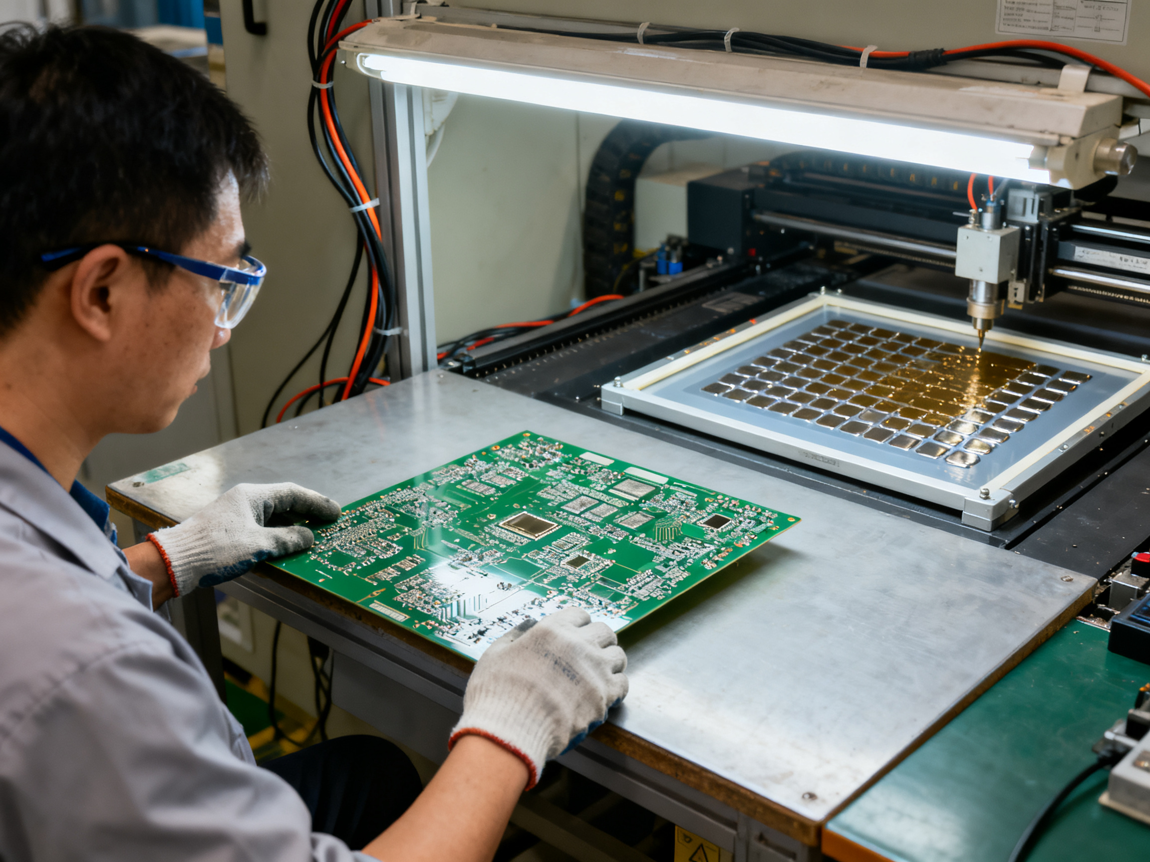
The stencil printer is where most defects get born. Excess paste causes bridging. Insufficient paste causes cold joints. Asymmetric deposits cause tombstoning.
Match your stencil design to your defect history. If bridges keep showing up on fine-pitch components, consider reducing aperture sizes or adding dog-bones for leaded parts. If you see insufficient solder on thermal pads, apertures might need enlarging.
Calibrate your printer regularly. Squeegee pressure, separation speed, and alignment all drift over time. We run verification checks every shift on high-volume runs.
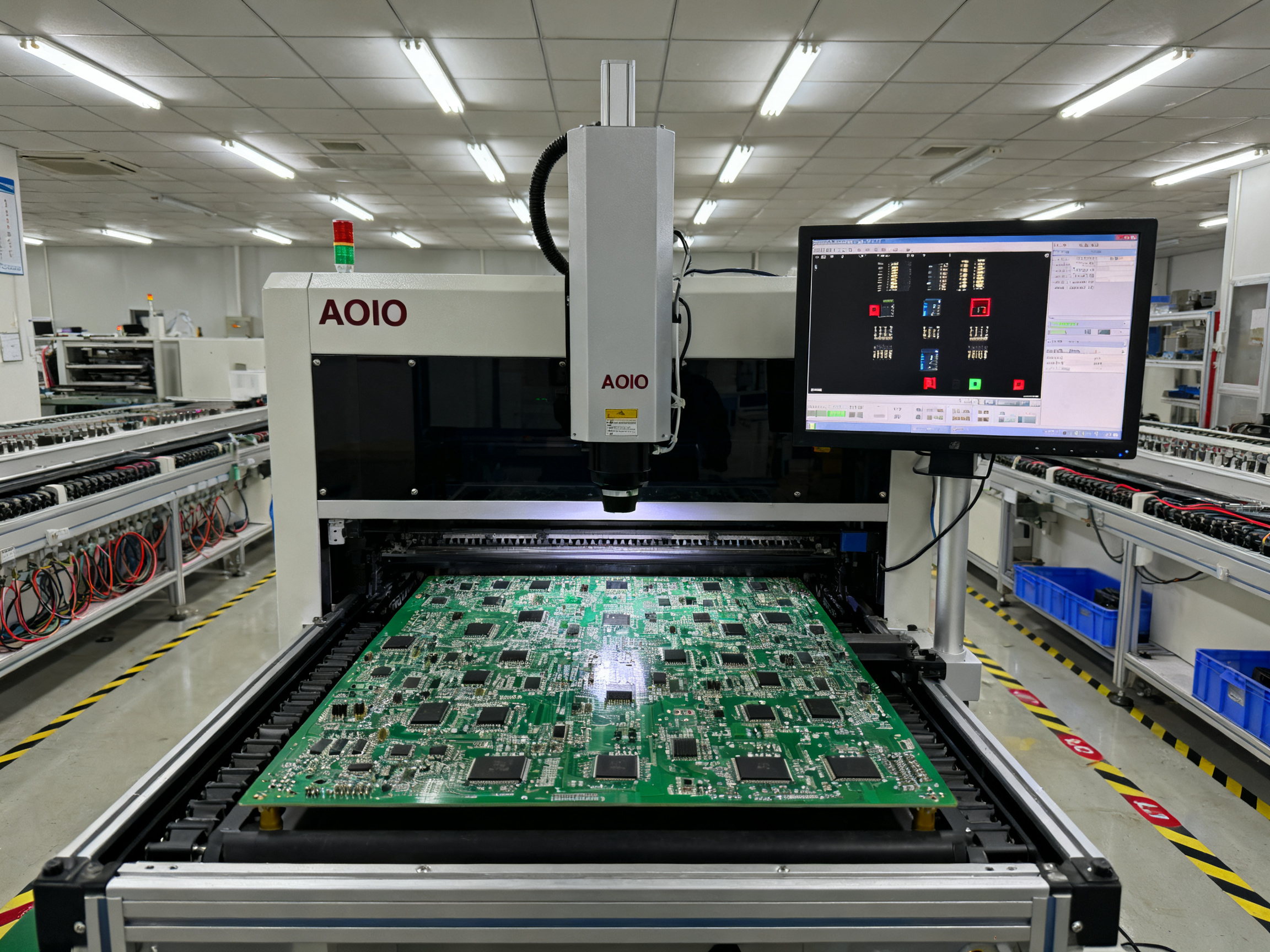
Use solder paste inspection (SPI) after printing. SPI catches volume and registration problems before components get placed. That feedback loop lets you adjust immediately rather than waiting for AOI after reflow.
Profile Development and Validation
Never trust setpoints. Always run a profiler with thermocouples attached to actual boards.
Place thermocouples where heat is hardest to reach: heavy copper areas, component centers, corners, and anywhere near temperature-sensitive parts. Different board locations heat at different rates.
Validate profiles with multiple boards before committing to production. One good run means nothing. You want to see consistent results across several assemblies.
Track your TAL, ramp rate, peak temperature, and cooling slope over time. If these drift outside tolerances, adjust conveyor speed or zone temperatures before defects escalate.
Equipment Maintenance
Preventive maintenance keeps everything running straight. Schedule regular calibration for oven zones, conveyor systems, and thermal monitoring equipment.
Check conveyor belts for wear and proper tension. A slipping belt changes transit time through zones, which directly changes your TAL. Conveyor issues often look like profile problems until you dig deeper.
Replace filters, check fans, and verify oxygen monitoring systems on nitrogen-capable ovens. Dirty equipment runs hotter, less evenly, and produces more escapes.
From Our Experience: Real-world defect patterns observed in production environments and quick diagnostic approaches. When you see recurring defects on the same component type or board location, start with the physical setup before touching profile settings. Nine times out of ten, the problem traces back to paste deposition, component placement, or pad geometry. Profile tuning is the last resort, not the first move.
Building Your Prevention Checklist
Lock down paste storage and lot traceability. Verify stencil design and printer calibration. Build thermal profiles using real thermocouple data on representative boards. Schedule preventive maintenance and track calibration dates. Use layered inspection with SPI, AOI, and X-ray for critical packages.
This sequence catches most defects before they cost you rework time. The oven is only as good as what you feed into it, so get the upstream steps right first.
Sun and Mountain SMT offers reflow ovens with built-in profiling support and closed-loop monitoring for shops serious about defect prevention. Contact our technical team to discuss your production requirements.## Conclusion: Optimizing Your Reflow Process for Quality and Efficiency
Reflow soldering sits at the heart of modern electronics manufacturing. The quality of your reflow process touches every board that leaves your line, and bad joints cost way more than the time spent getting things right the first time.
Getting reflow right comes down to a handful of things working together. You need proper solder paste handling, because degraded paste produces bad results no matter how perfect your oven settings become. You need optimized temperature profiles built from real thermocouple data, not guessed from what the machine display shows. You need equipment that matches your actual production requirements, whether that means high throughput for consumer work or precision control for automotive assemblies. And you need consistent process monitoring, because what you do not measure, you cannot improve.
Each of these pieces connects to the others. The best profile fails if your paste is old. The best paste wastes away on a poorly calibrated printer. The best printer does not help if your oven drifts outside tolerances. Strong reflow process control means watching all of it together, not chasing one variable while ignoring the rest.
If you are evaluating equipment upgrades or looking to sharpen your existing process, start with a clear picture of where you stand. Run thermal profilers on your current boards and compare results against paste datasheet recommendations. Audit your paste storage and handling practices. Check your defect pareto to see where problems actually come from. These steps usually reveal quick wins before you spend money on new equipment.
For companies running high-mix production or preparing for automotive and aerospace quality requirements, the investment in profiling tools, inspection equipment, and process documentation pays back through reduced rework and fewer field returns.
Sun and Mountain SMT offers reflow ovens built for both high-volume consumer assembly and precision-controlled automotive and aerospace applications. Their technical team can help match equipment to your specific production requirements.
Contact Sun and Mountain SMT to discuss your reflow equipment needs or request a process capability assessment for your production line.