
Published: 26 May 2026
Reading Time: 8 minutes
Reviewer: [Expert Name], [Credentials]
Understanding the Importance of Reflow Solder Profiles
Have you ever wondered why some circuit boards work perfectly while others fail right out of the factory? The answer often comes down to one thing: the reflow soldering profile.
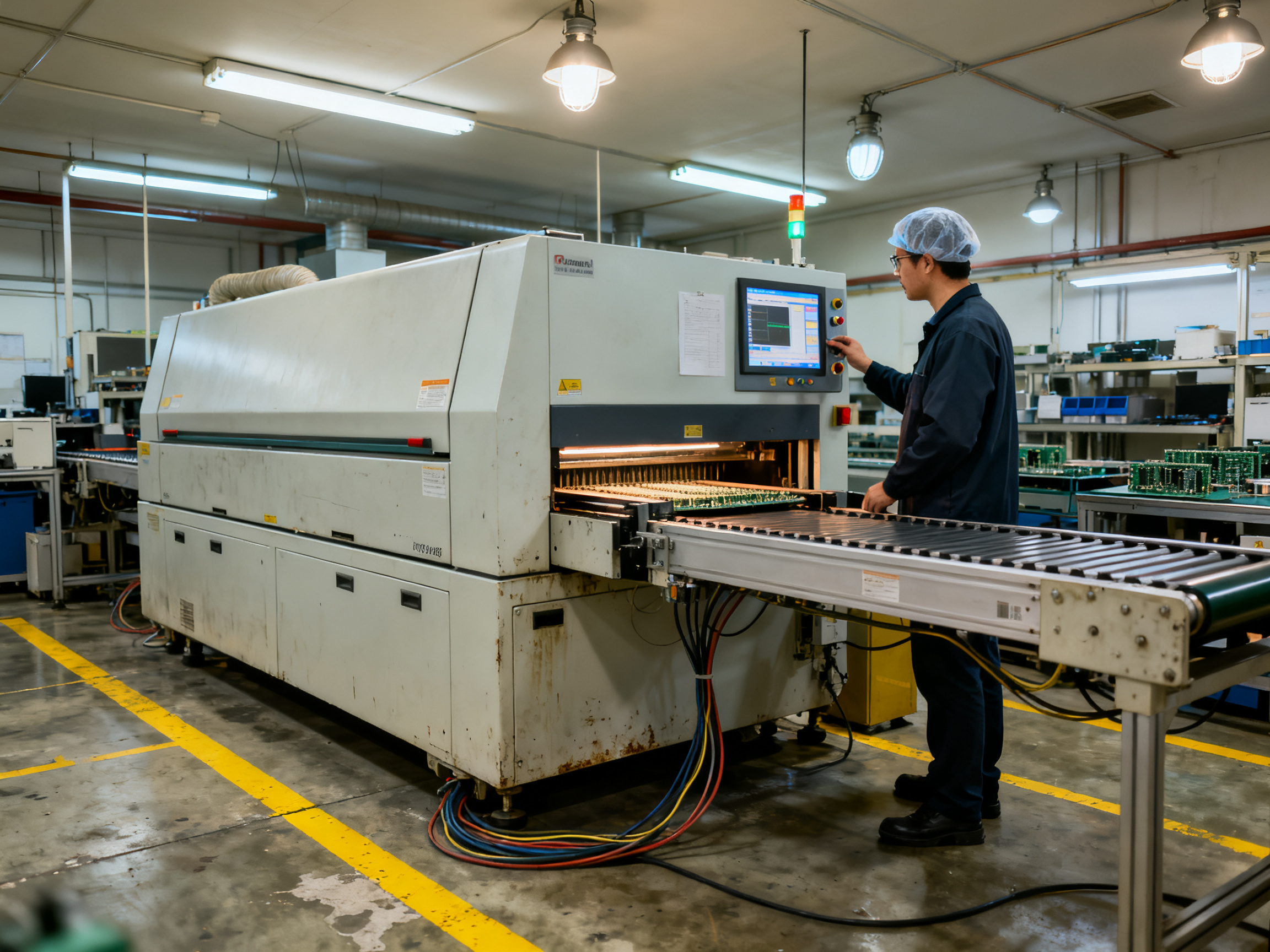
A reflow soldering profile is basically a detailed temperature roadmap that your PCB follows through the reflow oven. It controls how heat moves across your board, making sure solder melts at the right moment and cools down properly to form strong, reliable joints. Skip this step or mess it up, and you’ll deal with cold joints, tombstoning, or bridges that turn your assembly line into a nightmare.
Here’s the tricky part though: getting the profile right isn’t as simple as punching in some numbers. You have to balance heating speed against component sensitivity, deal with mixed materials on the same board, and make sure your oven performs consistently. That’s why engineers spend so much time fine-tuning these thermal profiles.
In 2026, the game has changed. With lead-free solders now standard everywhere and components getting smaller by the year, we’re seeing smarter profiling tools, real-time monitoring systems, and even vacuum-assisted reflow technology hitting the shop floor. In this guide, we’re going to break down how to build, measure, and optimize your reflow profile so your boards come out right every time.
Placeholder for Author Bio
About the Author: With over 15 years in electronics manufacturing, I’ve spent countless hours fine-tuning reflow profiles for everything from simple LED boards to complex multi-layer PCBs. When I’m not optimizing thermal profiles, I’m testing new solder pastes and mentoring production engineers on best practices. I believe there’s always a better profile waiting to be discovered.
Building an Effective Reflow Solder Profile
Building a solid reflow soldering profile means putting together a temperature-vs-time roadmap that your PCB travels through. Think of it like a cooking recipe, except instead of turning ingredients into dinner, you’re turning raw components into working circuits.
Here’s how you actually build one:
Step 1: Start with your solder paste datasheet
Every paste comes with recommended temperatures. These aren’t suggestions, they’re your starting point. Most lead-free pastes want a peak temperature around 245 to 260 degrees Celsius.
Step 2: Map out the four zones
The preheat zone gently raises the board temperature so moisture escapes without exploding any components. Then comes the soak zone where everything stabilizes at a lower temperature. The reflow zone is where solder actually melts, and cooling solidifies everything into place.
Step 3: Set your timing windows
Temperature changes per second matter a lot. Typical ramp rates sit between 0.5 and 3 degrees per second. Too fast and components crack from thermal shock. Too slow and you waste time or oxidize the board.
Step 4: Test with thermocouples
Slap a few thermocouples on a test board, run it through, and check your reflow profile graph against what you planned. Modern profiling software handles this automatically, giving you real-time feedback on how closely your actual profile matches your target.
Profiling tools from companies like Sun and Mountain SMT let you dial in settings and see results immediately. No more guessing.
Expert Tip: Start conservative with your temperatures and speeds. You can always push harder once you know your oven and board can handle it. Overly aggressive first profiles cause expensive failures.
What about different board sizes?
Larger boards need slower ramp rates because they hold heat differently. Smaller, denser boards with tons of components might need longer soak times to ensure everything reaches temperature evenly. We usually keep a library of tested profiles for common board sizes so we’re not starting from scratch every time.
The key is documentation. Write down every setting, every adjustment, every result. That way when you need to run the same job three months from now, you’re not relearning everything from scratch.
Measuring Reflow Oven Temperature Profiles
So you’ve built your target reflow profile on paper. Now comes the real test: seeing what actually happens inside that oven. This is where all your careful planning either pays off or needs adjustment.
The measurement setup matters
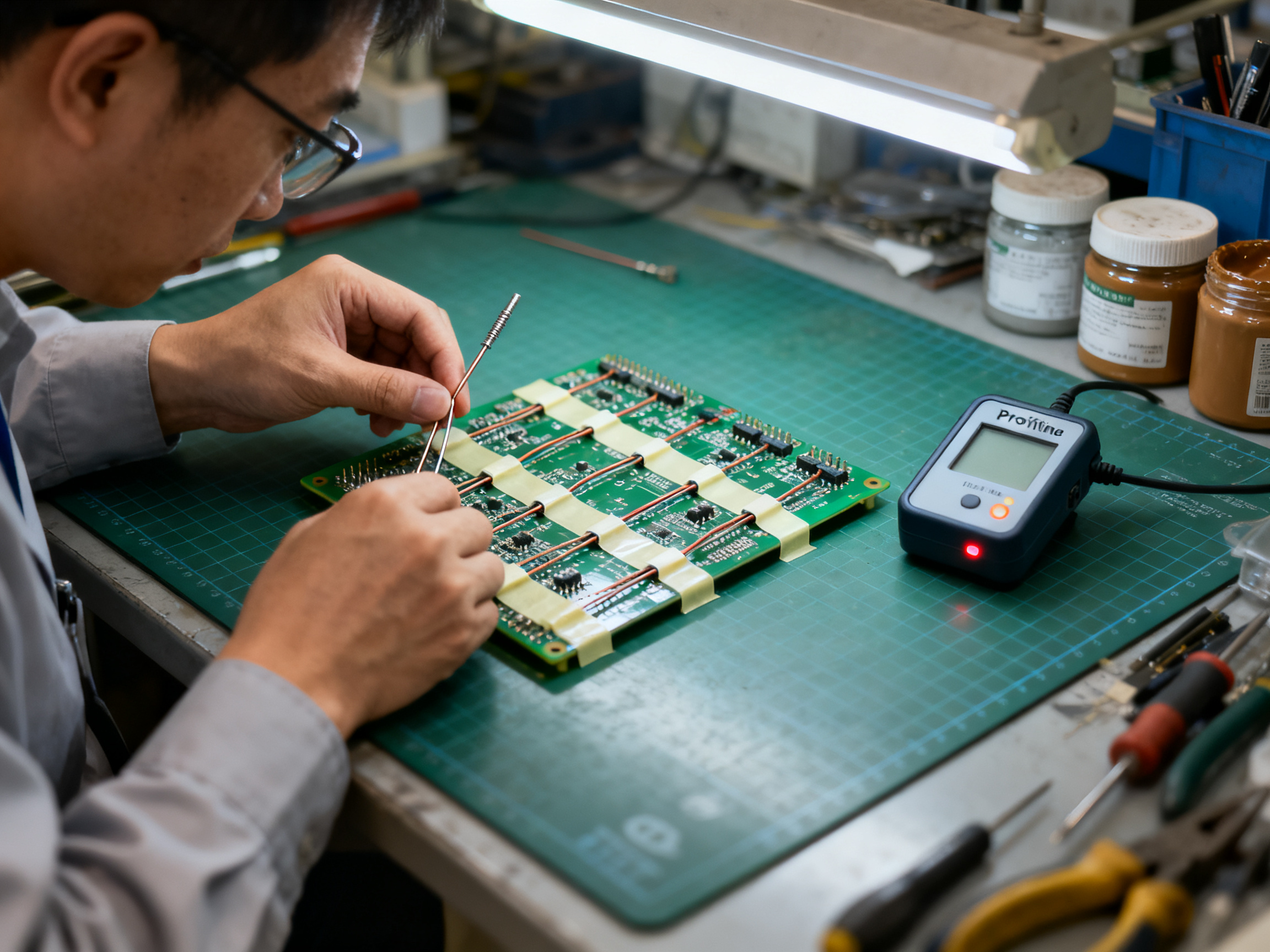
You can’t just eyeball temperatures. You’ll need thermocouples, which are basically tiny temperature sensors that attach to your PCB. We typically use 6 to 12 thermocouples per board, placed at corners, centers, and anywhere with heat-sensitive components. The goal is capturing both the hottest and coldest spots during the reflow process.
Modern profiling systems from companies like Sun and Mountain SMT have changed the game here. Instead of manual data logging, you get wireless thermocouple systems that stream real-time temperature data to your computer. The software plots everything automatically, giving you a reflow profile graph you can compare against your target in seconds rather than hours.
Getting accurate readings takes practice
Placement technique affects your results more than people realize. Thermocouples need to touch the component leads or solder joints directly, not just sit near them. We use high-temperature tape to secure each sensor, then run the board through just like a production piece.
One tip from experience: always measure at the start of every production shift. Ovens drift throughout the day as heating elements age and ambient conditions change. What worked Monday morning might read differently by Tuesday afternoon.
Analyzing your profile data
Once you’ve run your test board, the software spits out that beautiful reflow profile graph. Look for three things: are all zones reaching their target temperatures, is the time above liquidus consistent across the board, and does cooling follow the recommended slope?
Most profiling software will flag issues automatically. But here’s what nobody tells you: small deviations usually don’t matter. A 5-degree variance in one corner often produces perfectly good joints. It’s the big picture that counts, not perfection in every data point.
Pro Insight: Keep records of every profile measurement. That history becomes invaluable when troubleshooting failures months later or replicating jobs on different equipment. A solid documentation habit saves more headaches than any single perfect profile.
Optimizing Your Reflow Profile for Various Products
No two boards are exactly alike. A profile that works perfectly for a simple LED driver might fail spectacularly on a dense multi-layer board packed with BGA components. That’s why optimization matters so much in real-world SMT production.
Adapting profiles for different product types
The biggest variable is thermal mass. Heavy, large boards hold heat longer and need gentler ramp rates. We usually start at 1 degree per second for big assemblies and bump that up to 2-3 degrees for smaller, lighter boards.
Mixed assemblies create another challenge. When you have heat-sensitive connectors next to components that need serious reflow, you have to find the middle ground. One trick we use: split the board into thermal zones and adjust your oven’s zone settings to create a gradient. Some of the newer reflow ovens from companies like Sun and Mountain SMT let you program zone-by-zone temperature curves, which makes this easier than it used to be.
For lead-free assemblies (which is most of what we run in 2026), you’ll need to push peak temperatures higher, typically 245 to 260 degrees Celsius. The soak phase becomes more critical too. Rushing it risks thermal shock, and we definitely don’t want that.
Troubleshooting common issues
When something goes wrong, your reflow profile graph tells the story. Cold joints usually mean not enough time above liquidus or peak temperature running too low. Tombstoning points to ramp rates that are too fast. Bridging often comes from excess paste or a soak zone that isn’t stabilizing things properly.
Real-world example: We had a batch of automotive control modules failing last quarter. The issue was subtle, but checking the reflow profile revealed the cooling slope was too steep, creating thermal stress on one corner. A small adjustment to the cooling rate fixed everything.
Pro Insight: Keep a profile library for common board families. When you get a similar design, start from an existing profile and make incremental adjustments. This cuts debugging time dramatically compared to building from scratch every job.
The key is making small changes one at a time. Adjust temperature, run a test, check results. Don’t tweak five things simultaneously or you’ll never know what actually helped.
Future Trends in Reflow Soldering Profile Technologies
The reflow soldering world is changing fast. In 2026, we’re already seeing tech that would have seemed like science fiction a decade ago.
Real-time monitoring has become standard in high-end facilities. Instead of running test boards and checking graphs afterward, modern reflow ovens from companies like Sun and Mountain SMT now include built-in sensors that track temperature continuously during production runs. If something drifts out of spec, the system alerts you before bad boards pile up.
Vacuum-assisted reflow is another game changer. Traditional reflow leaves tiny voids in solder joints, which causes reliability problems down the road. Vacuum chambers built into newer ovens pull those voids out, creating stronger, more consistent joints. It’s not cheap yet, but for aerospace or automotive work where failure isn’t an option, the investment makes sense.
Looking ahead, I think we’ll see more AI-assisted profiling. Imagine software that analyzes your board layout, checks component heat sensitivity, and generates an optimized profile automatically. We’re not quite there, but the pieces are falling into place.
What won’t change is the need for good fundamentals. Better tools help, but understanding why your profile works still matters. The engineers who understand the basics will adapt fastest to whatever comes next.
The industry is also pushing toward tighter integration between design software and profiling tools. Soon your CAD files might upload directly to the reflow oven, which pulls the right profile settings automatically. Less setup time means more time making actual boards.
Conclusion and Expert Recommendations
Let’s wrap this up. After all the talk about temperatures, zones, and thermocouples, here’s what actually matters.
Build profiles from paste datasheets first. Don’t guess. Start with what the manufacturer recommends, then adjust based on your oven and board characteristics. Documentation is your friend here. Write everything down.
Measure constantly. Ovens drift. Conditions change. A profile that worked Monday might need tweaking by Friday. Run thermocouples at shift start, keep records, and compare results over time.
Optimize slowly. One change at a time. Ramp rate OR temperature OR soak duration. Never multiple variables at once. And remember, small deviations rarely cause failures. It’s the big picture that counts.
Start simple. If you’re new to reflow profiling, don’t jump straight into lead-free assemblies with BGAs. Build experience on forgiving boards first. Save the complex stuff for when you understand what your oven can actually do.
From Our Experience: The best profile is the one you can reproduce consistently. Perfect temperature curves mean nothing if you can’t hit them every single run. Focus on repeatability over theoretical optimization.
The tools keep getting smarter in 2026. Real-time monitoring, vacuum-assisted reflow, AI-assisted profiling they’re all becoming more accessible. But the fundamentals haven’t changed. Know your zones, measure your results, document everything, and adjust incrementally.
Now get out there and make some boards.
Quick Reference: Reflow Profile Zones
| Zone | Purpose | Typical Temp Range | Typical Duration |
|——|———|——————-|——————-|
| Preheat | Moisture removal, thermal equalization | 25 to 150°C | 60 to 120 seconds |
| Soak | Stabilization, flux activation | 150 to 200°C | 60 to 90 seconds |
| Reflow | Solder melting and wetting | 245 to 260°C peak | 30 to 60 seconds above liquidus |
| Cooling | Solidification of joints | 260 to 100°C | 30 to 90 seconds |
Note: Times and temperatures vary based on solder paste type, board complexity, and component sensitivity. Always defer to your paste manufacturer’s specifications first.