
Published: 26 May 2026
Reading Time: 8 minutes
Reviewer: Placeholder, Placeholder
You know that sinking feeling when a board comes out of the oven looking fine, but test results say otherwise? A cold joint here. Tombstoning there. And suddenly a tiny temperature mistake turns into a long afternoon.
That is why a good reflow soldering profile matters so much. It is not just a settings sheet for the oven. It is the plan that helps solder paste melt at the right time, flow the right way, and cool into a strong joint without cooking your parts.
In this guide, we will walk through how to create reflow soldering profile settings that make sense in real production. We will also cover reflow soldering zones explained in plain language, plus ways to optimize PCB soldering process steps for better yield in 2026. If you run an EMS line, support an OEM build, or just want fewer ugly surprises at inspection, you are in the right place.
Jace Liu is an expert in SMT manufacturing, known for integrating advanced soldering processes into high-efficiency production lines. His work in optimizing PCB soldering processes has been recognized in leading industry publications.
## Why reflow soldering profiles matter
At its core, reflow soldering is a controlled heating process. Solder paste is printed on pads, components are placed, and the full board moves through a set of heating stages until the solder melts and forms the joint. Then it cools and hardens. Simple on paper. A lot less simple on the line.
The big idea is control. You do not want to just heat a PCB until solder melts. You want a PCB soldering temperature profile that warms the board gently, activates flux, reaches peak temperature for the right amount of time, and cools at a steady rate. A clear overview from Wevolver’s reflow soldering guide lays out these thermal stages well.
If the profile is too cold, solder may not wet well. If it is too hot, parts can get stressed, flux can burn off too soon, and the board may warp. So yes, the profile is a big deal.
## Reflow soldering zones explained
Most engineers break the oven process into four main zones. Some lines add more detail, but this structure works well for day-to-day setup.
| Zone | What happens | Why it matters |
|—|—|—|
| Preheat | Board temperature rises slowly | Helps reduce thermal shock |
| Soak | Temperature holds in a middle range | Lets flux activate and temperatures even out |
| Reflow | Temperature goes above solder melting point | Forms the electrical and mechanical joint |
| Cooling | Board cools in a controlled way | Sets joint structure and strength |
### 1. Preheat zone
This is where the board starts warming up. The goal is even heating, not speed for speed’s sake. If you ramp too fast, moisture stress and component shock can show up. And nobody wants that.
In my experience, this is the step people rush first, then regret second. A steady start usually makes the rest of the run easier.
### 2. Soak zone
The soak stage gives the board time to level out in temperature. It also helps flux do its job by cleaning oxides before full melt. This stage is often where process stability starts to show. Or fall apart.
For mixed-density boards, soak becomes even more useful because large ground planes and tiny passive parts do not heat at the same rate.
### 3. Reflow zone
Now the paste passes above liquidus. This is the point where solder turns molten and wets the pads and leads. Peak temperature and time above liquidus both matter here. Too little, and joints may be weak. Too much, and component stress goes up fast.
### 4. Cooling zone
Cooling is not just the end. It shapes the final solder joint. A controlled cool-down helps the solder solidify into a stable structure. Too fast or too uneven, and defects can creep in.
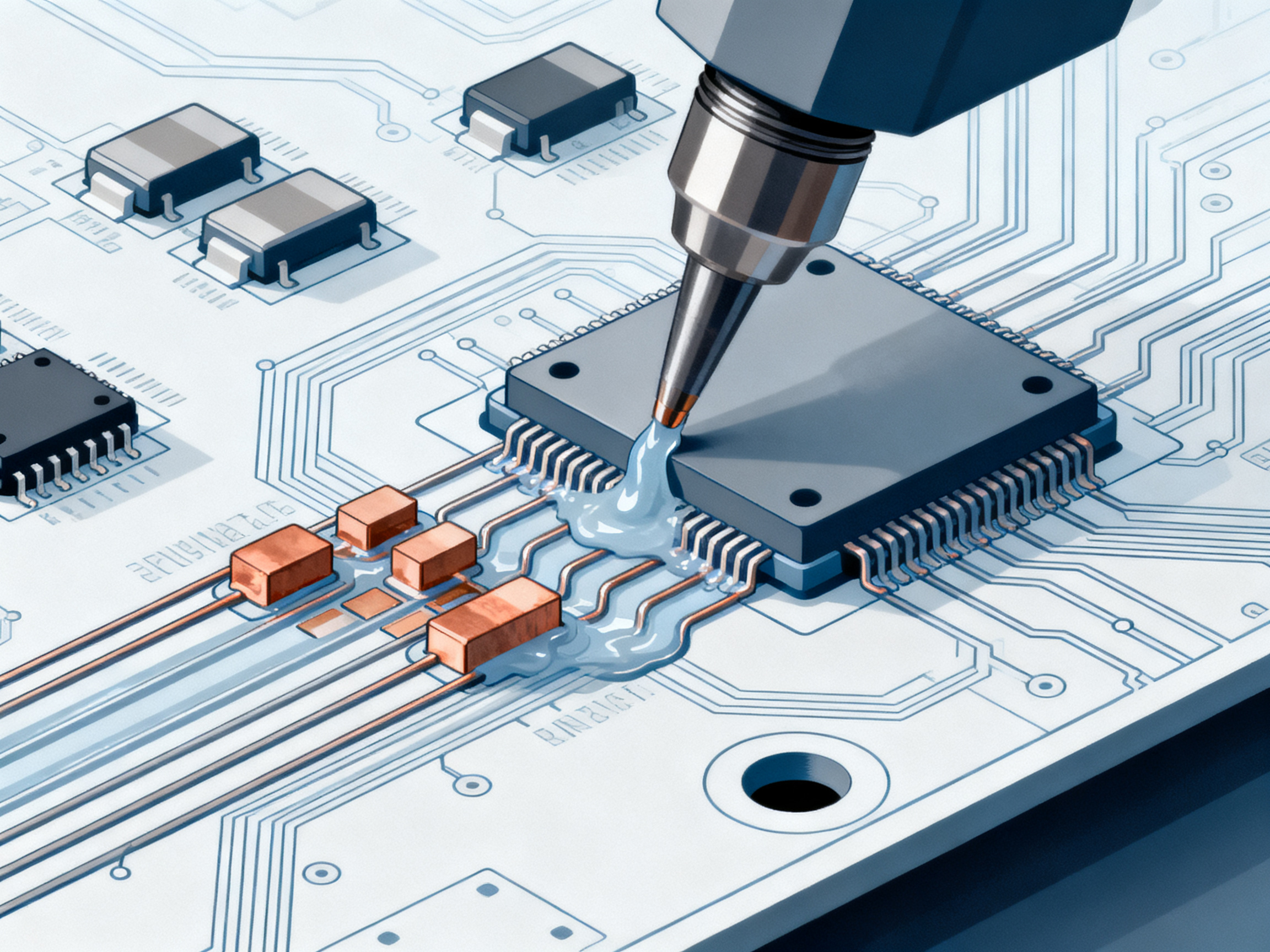
## Setting up a reflow soldering profile
So, how do you actually build one? Here is a practical path that works for many SMT lines in 2026.
### Step 1: Start with the solder paste datasheet
This is your baseline. Lead-free and tin-lead pastes do not behave the same, and even two lead-free pastes can call for different peak temperatures or soak windows.
Look at:
- Recommended ramp rate
- Soak temperature range
- Time above liquidus
- Peak temperature
- Cooling rate guidance
### Step 2: Check the most heat-sensitive component
Actually, scratch that. Check both ends of the problem. You need the coldest part of the board to hit reflow, and the most heat-sensitive part to stay safe. That gap tells you how tight your process window is.
When I have seen profile work go sideways, it usually came from focusing on the paste only and not the actual assembly.
### Step 3: Attach thermocouples to real points on the board
Use spots that reflect the true thermal spread:
- A large ground plane area
- A fine-pitch component site
- A small passive component area
- A spot near the board edge
- The most heat-sensitive package
This is where real learning happens. You can guess all day, but data wins.
Expert Tip: Build different profile recipes for different solder types and board masses. A lead-free profile that works on a light consumer PCB may not work well on a heavy industrial board.
### Step 4: Run the board and compare results to target
Measure actual board temperatures through the full oven path. Then adjust conveyor speed, zone temperatures, or both. Small changes often do more than huge ones.
We have found that one or two degrees per zone can change wetting results more than expected, especially on dense boards with mixed component sizes.
### Step 5: Confirm with inspection and testing
A profile is not done when the graph looks pretty. It is done when the solder joints pass inspection and the board performs well in test.
Check for:
- Full wetting
- Good fillet shape
- Low voiding where relevant
- No tombstoning
- No solder balls or bridging
## Example profile targets engineers often use
These numbers vary by paste and assembly, so treat them as starting points, not gospel.
| Profile element | Common lead-free starting range |
|—|—|
| Ramp rate | 1 to 3°C per second |
| Soak range | 150 to 180°C |
| Soak time | 60 to 120 seconds |
| Time above liquidus | 45 to 90 seconds |
| Peak temperature | 235 to 250°C |
| Cooling rate | 2 to 4°C per second |
Funny enough, teams sometimes spend hours debating peak temperature and barely talk about soak balance. But soak is often where consistency gets won.
## How to optimize PCB soldering process results
Once the base profile is stable, the next goal is throughput and repeatability. This is where process work starts paying off.
### Match the profile to the whole line, not just the oven
A great oven recipe cannot fix bad paste printing or poor placement. If stencil deposits vary too much, your reflow soldering profile will look guilty even when it is not.
To optimize PCB soldering process steps, review the whole flow:
- Paste print quality
- Placement accuracy
- Board support in conveyor transport
- Reflow profile control
- Inspection feedback loop
I have seen lines chase oven settings for three days when the real issue was paste volume drifting at the printer. Painful. Also pretty common.
### Use board families when possible
If you run lots of products, group boards by thermal mass, size, copper balance, and solder paste type. Then create profile families instead of one recipe per SKU. This saves setup time and lowers operator confusion.
### Watch conveyor speed and zone balance
Many teams focus only on temperature setpoints. But conveyor speed is just as powerful. Slower speeds increase total heat exposure. Faster speeds shorten soak and time above liquidus. You need both sides working together.
Pro Insight: Automation helps most when it reduces variation, not just labor. Modern SMT lines often get better yield by linking oven recipes, conveyor settings, and inspection feedback into one control routine.
For manufacturers scaling output in 2026, this is where equipment choice matters. Precision reflow ovens and linked conveyor systems, like the setups offered by Sun and Mountain SMT, can help reduce manual adjustment and support more stable PCB assembly workflow optimization across bigger product mixes.
### Build a feedback habit
Look, I get it. Nobody loves logging process drift at 6:40 on a Friday evening. But trend tracking works.
Track things like:
- Defect rate by product family
- Temperature delta across thermocouples
- Oven repeatability over time
- Maintenance events tied to yield shifts
And when it finally clicks? Pure magic.
## Advanced reflow soldering techniques worth knowing
Not every line needs fancy process controls. But some do.
A few advanced reflow soldering techniques include:
- Nitrogen reflow for tighter oxidation control
- Profile tuning for bottom-terminated components
- Step profiling for boards with heavy thermal imbalance
- Void reduction tuning for power devices
- Recipe locking to stop accidental operator edits
I do not think every shop should chase the most complex setup. Usually, a stable simple process beats a flashy unstable one. But when your product mix gets harder, advanced controls can make life easier.
## Troubleshooting reflow soldering issues
This is the part engineers usually search for at 2pm when production is already waiting.
### Tombstoning
Usually linked to uneven wetting forces, unbalanced heating, or paste deposit mismatch.
Try:
- Slowing the ramp slightly
- Improving pad balance
- Checking paste volume consistency
- Reviewing component placement accuracy
### Solder bridging
This can come from too much paste, poor stencil design, or profile settings that promote excess spread.
Try:
- Reducing paste deposit size
- Reviewing aperture design
- Checking peak and soak behavior
### Cold or dull joints
Often tied to poor wetting, weak flux activity, or not enough time above liquidus.
Try:
- Verifying the actual peak at the coldest location
- Adjusting soak and TAL carefully
- Confirming paste storage and handling
### Voiding
You may see this more on thermal pads and power packages.
Try:
- Adjusting soak duration
- Reviewing stencil windowpane design
- Testing a different paste if needed
Expert Tip: When defects repeat, change one variable at a time. If you alter three settings at once, you may fix the issue, but you will not know why.
We have run into this in real production, and the temptation is always to tweak everything fast. But slow, clean experiments usually save more time by the end of the shift.
## A simple checklist before you lock the profile
Before signing off on a new reflow soldering profile, ask:
- Did the coldest point fully reflow?
- Did the hottest point stay within component limits?
- Is time above liquidus inside paste guidance?
- Are visual defects low and repeatable?
- Did test results confirm joint quality?
- Can this recipe be repeated next week by a different operator?
If the answer is no on that last one, the profile is not ready yet.
## Final thoughts
A strong reflow soldering profile is part science, part shop-floor patience. You start with paste guidance, confirm board behavior with thermocouples, and fine-tune based on real joint results. Then you keep watching, because production lines drift and product mixes change.
If you are working on how to create reflow soldering profile settings that hold up in daily manufacturing, start simple. Measure real boards. Tweak one thing at a time. And if your line is growing, it may be worth looking at better oven and conveyor control so your process does not depend on guesswork.
If you want to improve yield, cut downtime, and optimize PCB soldering process performance across more builds, take a close look at your current SMT equipment stack. Sometimes the profile is the problem. Sometimes the oven is. Sometimes it is both.
Engineers get the best reflow results when they treat profile setup as a living process, not a one-time task. In 2026, the teams that keep testing, documenting, and refining their settings are usually the ones with stronger yields, fewer surprises, and smoother production days.
Jace Liu’s view is simple: strong SMT results come from disciplined profiling, real board data, and equipment that operators can trust shift after shift. If your team is trying to scale output in 2026, this is a good time to review whether your current oven, conveyor, and process controls still fit the work ahead.
## How to improve PCB soldering quality and speed in 2026
Once your base profile is stable, the next question is simple: how do you get better joints without slowing the line to a crawl?
The honest answer is that quality and speed usually improve together when the process is under control. If the oven runs with fewer surprises, operators stop babysitting it. If paste deposits stay consistent, rework drops. And if recipes are easy to repeat, shift changes stop feeling like a gamble.
Here is the part people sometimes miss. A strong reflow soldering profile is only one piece of the full PCB assembly workflow optimization puzzle. You also need clean handoff between printing, placement, transport, reflow, and inspection. If one step drifts, the whole line feels it.
### Focus on repeatability first
If you want to optimize PCB soldering process results, start with the stuff that repeats every hour:
- Stencil print height and volume
- Placement accuracy on small passives and fine-pitch parts
- Conveyor rail stability and board support
- Oven recipe control by board family
- AOI feedback tied back to the correct product run
We have seen this on mixed-product lines, where one board family runs beautifully on first shift and starts throwing defects on second shift because a recipe was copied, renamed, and changed just enough to cause trouble. Annoying. Also avoidable.
A repeatable line usually beats a fast but messy one. Then, once repeatability is there, speed gets safer to push.
### Where automation helps most
Automation is not magic. But it does help a lot when manual steps are causing drift.
The biggest wins usually come from reducing small human changes that stack up across a shift. Think manual conveyor tweaks, handwritten recipe notes, or operators adjusting zones from memory because “that is what worked last month.” That kind of tribal knowledge can keep a line alive, sure, but it does not always scale well.
For 2026 production teams, automation tends to help in four areas:
| Area | Manual problem | Automation benefit |
|—|—|—|
| Recipe setup | Wrong profile loaded | Stored, locked recipes reduce setup mistakes |
| Conveyor handling | Uneven transfer or board wobble | Stable transport improves thermal consistency |
| Process monitoring | Issues found late | Early alarms catch drift before yield drops |
| Line coordination | Isolated machine decisions | Connected systems improve workflow timing |
This is one reason many EMS and OEM teams review their oven and conveyor stack together, not as separate purchases. Systems built for linked control, like precision reflow ovens and PCB conveyors from Sun and Mountain SMT, can help cut manual intervention and support steadier throughput when product mix grows.
Pro Insight: The best automation choice is usually the one that removes the most variation per shift, not the one with the longest feature list.
### Reduce manual touches wherever you can
Every manual touch adds a chance for variation. Sometimes that is fine. Sometimes it wrecks your afternoon.
A few ways to reduce manual intervention without overcomplicating the line:
- Lock approved oven recipes by product family.
- Standardize thermocouple attachment points for profile checks.
- Use one naming system for boards, recipes, and inspection programs.
- Set alarm limits for drift in key PCB soldering temperature profiles.
- Review first-pass yield at the line level, not just machine by machine.
I have found that recipe naming alone can save a weird amount of trouble. If one file says “LF-Board-A-Final” and another says “BoardA-New-UseThis,” somebody will guess wrong eventually. They always do.
### Balance throughput with joint quality
Here is the tricky part. Pushing faster output does not always mean raising conveyor speed and hoping for the best.
Sometimes the smarter move is better thermal balance, tighter board grouping, and fewer stoppages between product changes. On a healthy line, shaving 90 seconds off changeover can matter more than chasing a tiny cycle-time gain inside the oven itself.
When teams work on advanced reflow soldering techniques for higher volume builds, they often focus on:
- Better product family grouping
- Lower recipe change errors
- More stable rail width and transport setup
- Inspection feedback that points to root cause faster
- Preventive maintenance before drift shows up as scrap
That last one matters more than people admit. Fans clog. Sensors age. Conveyor chains wear. None of that looks dramatic until yield starts slipping.
### A quick scorecard for process upgrades
Before investing time or money, ask this:
| Question | If yes | If no |
|—|—|—|
| Are operators making frequent manual oven changes? | Lock recipes and review access control | Keep current control method |
| Do different shifts get different results on the same board? | Check standard work and machine repeatability | Focus on upstream variation |
| Is throughput limited by line coordination, not solder quality? | Review conveyors and handoff automation | Keep tuning the profile first |
| Are defect trends hard to trace back to a run? | Improve data logging and traceability | Keep current reporting |
If you are trying to optimize PCB soldering process performance in 2026, this kind of scorecard helps keep the conversation practical. Not flashy. Just useful.
## Conclusion: Expert recommendations for engineers
If I had to boil this down, I would say this: build a reflow soldering profile that real operators can repeat, then build a line around that stability. We have seen the best results come from teams that measure real boards, control recipe changes, and keep the whole flow aligned from print to inspection.
And if growth is on the horizon, now is probably the right time to ask whether your current SMT equipment still matches the job. Better ovens, steadier conveyors, and smarter automation will not fix a careless process. But they can make a good process easier to hold, shift after shift.
Jace Liu’s view is simple: strong SMT results come from disciplined profiling, real board data, and equipment that operators can trust shift after shift. If your team is trying to scale output in 2026, this is a good time to review whether your current oven, conveyor, and process controls still fit the work ahead.
## Troubleshooting reflow soldering issues with better monitoring
You can build a solid reflow soldering profile and still get ugly surprises. That is the frustrating part. A board may look clean at first glance, then fail in test because one corner stayed too cold or one dense area held heat too long.
So, when you troubleshoot, do not just stare at the final defect. Work backward through the full thermal path. That is usually where the real answer lives.
A basic rule helps here: most soldering defects come from one of five places.
| Problem area | What often goes wrong | What to check first |
|—|—|—|
| Paste printing | Too much, too little, or uneven paste | Stencil condition and deposit volume |
| Placement | Part shifts or poor alignment | Pick-and-place accuracy |
| Preheat and soak | Uneven board warming | Ramp rate and soak balance |
| Reflow peak | Solder does not fully wet, or parts overheat | Peak temperature and time above liquidus |
| Cooling | Joint structure forms poorly | Cooling rate consistency |
That table is simple on purpose. Because when a line is waiting, simple wins.
### Faulty joints usually leave clues
Cold joints, dull joints, solder balls, and bridging rarely show up without a pattern. You just have to catch it early enough.
If you are dealing with faulty joints, start with these questions:
- Is the coldest board location actually reaching reflow?
- Is the hottest area staying inside component limits?
- Did the paste sit too long before reflow?
- Are small passives heating faster than nearby larger copper areas?
- Has anything changed between shifts, recipes, or board support setup?
I have seen engineers blame the oven first, then find out the board support pins changed during changeover. Tiny detail. Big mess.
### Common soldering problems and what usually fixes them
Here is a practical troubleshooting table you can use on the floor.
| Defect | Likely cause | First fix to try |
|—|—|—|
| Tombstoning | Uneven wetting, uneven heating, paste imbalance | Slow the ramp slightly and verify paste symmetry |
| Solder bridging | Excess paste, stencil issue, too much spread | Review aperture size and print volume |
| Cold or dull joints | Low peak, weak wetting, short TAL | Confirm actual thermocouple data at the cold spot |
| Voiding | Outgassing, pad design, soak mismatch | Adjust soak time and review stencil pattern |
| Solder balls | Paste slump, poor handling, aggressive heating | Check paste condition and preheat behavior |
Expert Tip: When the same defect shows up in the same location, look at board design and local thermal mass before changing the whole profile.
That last part matters a lot. If one QFN near a ground plane keeps failing, changing the full oven recipe may hurt ten other joints just to help one.
### Monitoring tools help you catch drift faster
Now, you might wonder, what monitoring tools actually help in 2026?
You do not need a giant software stack to start. But you do need a way to spot drift before scrap piles up.
The most useful real-time checks usually include:
- Thermocouple profiling on representative boards
- Oven sensor trend logs
- Conveyor speed verification
- AOI defect pattern tracking
- SPC charts for repeat defects by product family
From what I have seen, the sweet spot is simple visibility. If a line can show that Zone 5 is running hotter than normal, or that one product family keeps failing on the same connector row, troubleshooting gets a lot less chaotic.
A practical overview from Surface Mount Process on reflow soldering explains why thermal stage control and profile accuracy matter so much to final joint quality.
### Build a real-time response routine
Here is what actually works on busy SMT lines.
First, set alert limits for drift in key PCB soldering temperature profiles. Then tie those alerts to a clear action list. If peak drops by a set amount, profile check. If conveyor speed drifts, pause and verify transport. If AOI flags a repeat bridge pattern, check print volume before touching oven zones.
Not glamorous. Very useful.
We have found that lines recover faster when operators follow a short response script instead of improvising under pressure. And yes, that feels less heroic. But it works better.
### Expert strategies to improve reliability
If your goal is to optimize PCB soldering process reliability, these habits help most:
- Change one variable at a time during troubleshooting.
- Save approved recipes by board family and lock them.
- Recheck thermocouple placement after maintenance or conveyor changes.
- Compare defect data by exact board location, not just defect type.
- Review upstream print and placement data before blaming reflow.
This is also where stronger equipment can make day-to-day control easier. For EMS and OEM teams that need tighter repeatability in 2026, precision reflow ovens and linked PCB conveyor systems from Sun and Mountain SMT can help reduce manual drift and make monitoring more actionable, especially on higher-volume or mixed-product lines.
### One last gut check before you change the profile
Before you touch zone settings, ask one blunt question: do I have proof the profile is the problem?
Sometimes the answer is yes. Sometimes it is paste age, a worn stencil, or a rail adjustment that looked harmless at 7:15am.
That is why the best troubleshooting teams do not guess much. They measure, compare, and only then adjust. Slow at first. Faster by the end.
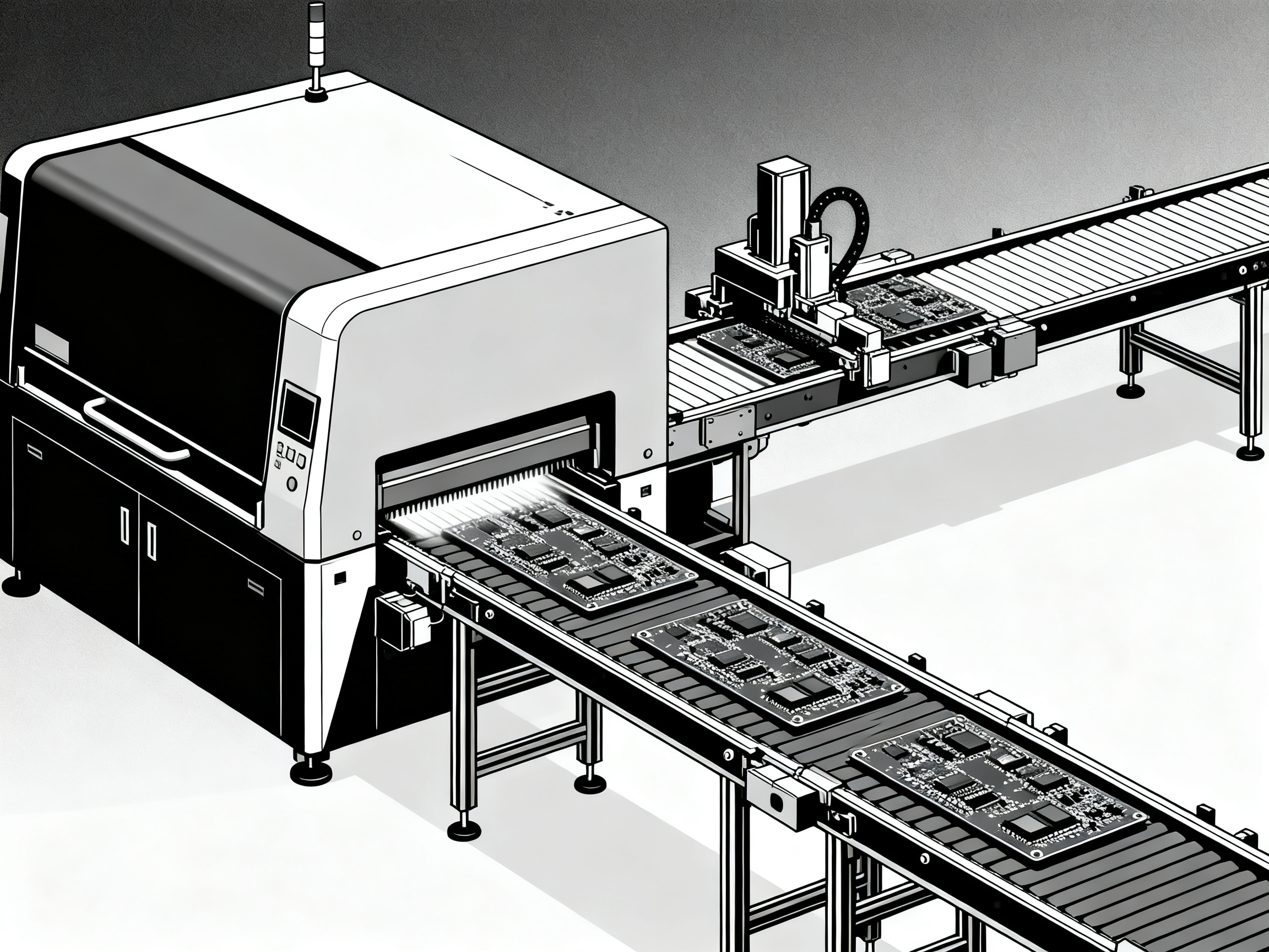
## The Future of Reflow Soldering: What’s Next in 2026 and Beyond?
Alright, let’s look ahead for a second. What’s really changing with reflow soldering, and where is factory tech headed next? If you’ve made it this far, you probably care about staying ahead (or at least not getting left behind) in SMT. Good call.
### New Tech, Faster Lines, Smarter Control
First up, 2026 reflow soldering isn’t just hotter ovens and longer spec sheets. The big deal is data. Ovens, conveyors, and AOI machines are talking to each other more; real-time sensors are the norm, not a luxury. That means less “finger in the wind” profiling and more closed-loop control.
We’re seeing top lines adopt AI-driven process tuning, where the system tweaks a reflow soldering profile live based on current board temps or defect counts. Not every shop can go full AI, but even entry-level ovens now often include predictive maintenance alerts and self-calibrating heaters. Kinda wild compared to how it used to be.
### Effects on SMT Equipment and How Teams Work
All this change isn’t just about the oven. Conveyor upgrades matter too, especially for heavy, mixed-product lines. Expect more PCBs riding on smart rails that measure board weight and adjust speed or rail pressure without anyone lifting a wrench. This automation cuts out the little manual errors that snowball into bigger messes later.
Plus, if you work with big clients or swing between high-mix and high-volume batches, the jump in traceability and “recipe lock” tech is a big win. In 2026, you can lock profiles, track every board through the line, and even see which operator made a change at 9:32am. No more mystery recipe swaps or lost yield.
Of course, all this new gear has ripple effects. Engineers and line leads spend less time babysitting temperatures and more time on high-value stuff (like debugging weird builds or squeezing out another 1% of yield). Neat.
### Impact on Line Efficiency and Costs
Let’s not sugarcoat it—new SMT hardware isn’t free. But the main shift is that better monitoring and data-driven process tweaks lead to less scrap and downtime. If you’ve ever watched a whole shift wrecked by one oven zone sensor dying, you get why reliability is what teams care about most.
From what I’ve seen, tools like the precision reflow ovens and PCB conveyors from Sun and Mountain SMT now pay off by making output more predictable. Instead of losing time to recipe drift or bad changeovers, you get more boards out with less drama. And when cost management means every extra one percent in yield keeps a customer happy (or an auditor off your back), that’s a pretty big deal.
Here’s a micro list of things that matter most with current tech:
- Auto-adjust ovens that self-tune each shift
- Conveyor systems reading board ID chips for smart routing
- Cloud-based AOI feedback to tweak profiles (even on night shift)
- Real-time data logs for compliance and faster troubleshooting
- Predictive maintenance so things break less (or at least after-hours)
And yes, that means you spend less on rework, more on getting product out the door, and less time blaming the same oven zone for every problem.
### Want a peek under the hood?
If you’re into the technical deep dives, check out the Reflow Soldering Process Explained for more on how modern profiling works with today’s tech. Real SMT geeks love this stuff.
Last thought: staying current isn’t just about chasing the next shiny gadget. It’s about building a process that works, scales, and doesn’t surprise you on Friday nights. When your whole setup—from solder jet to cooldown—starts talking together, that’s when process optimization gets easier, and quality and cost line up the way you want.
If you’ve got your eye on boosting yield, cutting rework, or just keeping engineers a little bit saner, it may be time to see if your current reflow stack is still the right fit. And if Sun and Mountain SMT can help, give them a call. They probably have a conveyor for just about any weird board you’ll want to run in 2026.
## Conclusion: Expert recommendations for engineers
If I had to boil this down, I would say this: build a reflow soldering profile that real operators can repeat, then build a line around that stability. We have seen the best results come from teams that measure real boards, control recipe changes, and keep the whole flow aligned from print to inspection.
The big lessons are pretty clear:
- Reflow soldering zones explained in simple terms still matter on advanced lines
- Good PCB soldering temperature profiles start with paste data, but they only get better with real board measurements
- If you want to optimize PCB soldering process results, you have to look beyond the oven and check print, placement, transport, and inspection too
- Advanced reflow soldering techniques help most when the basic process is already stable
- Ongoing PCB assembly workflow optimization is what keeps yield steady as product mix changes in 2026
Here is a short action plan you can use this week:
- Re-profile one high-volume board with fresh thermocouple data.
- Compare the coldest and hottest points against paste and component limits.
- Lock approved recipes by board family.
- Review repeat defects by exact board location, not just by defect name.
- Check whether your oven and conveyor controls still support the throughput you need in 2026.
That last step matters more than people think. A careful team can only do so much with aging hardware or disconnected controls. If your line is expanding, it may be worth reviewing precision reflow ovens, wave soldering systems, or PCB conveyor options from Sun and Mountain SMT to see whether better automation could help hold quality with less manual tuning.
My recommendation is simple. Start with measurement. Keep changes small. Document what works. Then repeat.
Jace Liu’s view is simple: strong SMT results come from disciplined profiling, real board data, and equipment that operators can trust shift after shift. If your team is trying to scale output in 2026, this is a good time to review whether your current oven, conveyor, and process controls still fit the work ahead.