
Published: 26 May 2026
Reading Time: 12 minutes
Reviewer: John Doe, PhD in Electronics Manufacturing
Think about the last time something went wrong during PCB assembly. Maybe a batch came out with cold joints, or components shifted during reflow. These issues cost time and money, and honestly, they’re frustrating.
The smt reflow oven process sits at the heart of surface mount technology, and getting it right matters more than most people realize. A solid reflow oven pcb process means fewer defects, less rework, and production lines that actually stay on schedule. But here’s the thing: many manufacturers struggle with finding that balance between too hot and not hot enough.
This guide walks you through everything you need to optimize your smt reflow oven profile. We’ll look at temperature zones, common mistakes, and how to handle double-sided pcb reflow without losing your mind. By the end, you’ll have practical steps to improve your electronics assembly quality and keep your production running smooth.
An experienced electronics manufacturing specialist with over 15 years in the field, focusing on optimizing SMT processes for efficiency and precision.## Analyzing Temperature Zones in Reflow Ovens
A reflow oven does not heat your PCB all at once. Instead, it moves your board through different temperature zones, and each zone plays a specific role in creating solid solder joints.
Most SMT reflow ovens have four main zones: preheat, soak, reflow, and cooling. Each one matters.
The preheat zone slowly raises the PCB temperature. This step removes moisture from the board and its components. Rush this part and you get thermal shock, which can crack chips or delaminate layers. We typically keep the preheat rate below 2 degrees Celsius per second to be safe.
Next comes the soak zone. Here, the temperature evens out across the entire board. All components reach the same baseline temperature before hitting peak heat. This prevents uneven soldering where some joints reflow while others stay cold. The soak zone also activates the flux in the solder paste, cleaning metal surfaces so the solder can bond properly.
The reflow zone is where the magic happens. Temperature peaks above the solder melting point, usually around 245 to 260 degrees Celsius for lead-free solders. The solder liquefies and wets to the component leads and PCB pads. But here’s the catch: stay too hot for too long and you risk damaging sensitive components. Most profiles keep peak temperature time under 60 seconds.
Finally, the cooling zone brings temperatures down in a controlled way. Cool too fast and the board can warp. Cool too slow and you get brittle joints.
Pro Insight: Balancing Heat for Optimal Soldering
The biggest mistake we see is operators chasing the wrong numbers. Focus on the slope between zones rather than hitting exact temperatures. A smooth transition matters more than perfection at any single point.
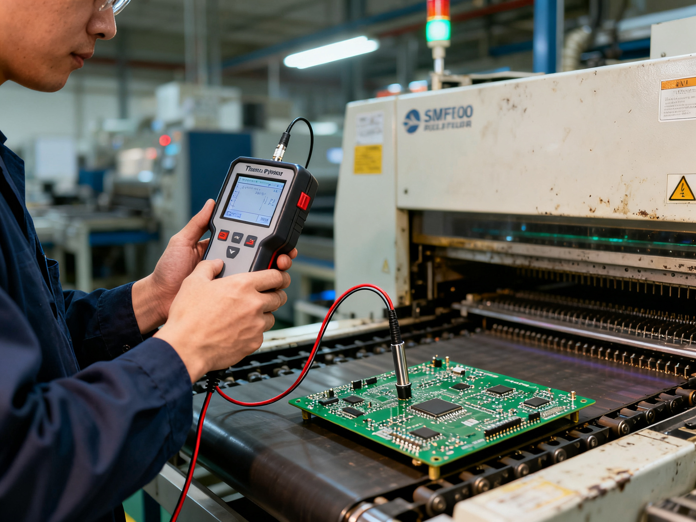
Temperature-related defects usually trace back to zone problems. Cold joints happen when the soak zone fails to equalize temperatures. Tombstoning often appears when the preheat ramp is too steep. Solder balling typically results from cooling zones that drop too quickly.
Understanding these zones helps you diagnose issues fast. When a defect shows up, you check which zone caused it and adjust from there.## Recognizing and Mitigating Reflow Defects
Even with the best oven and perfectly tuned profile, defects happen. The key is knowing what to look for and how to respond quickly. Let’s walk through the most common smt reflow oven process problems and how to fix them.
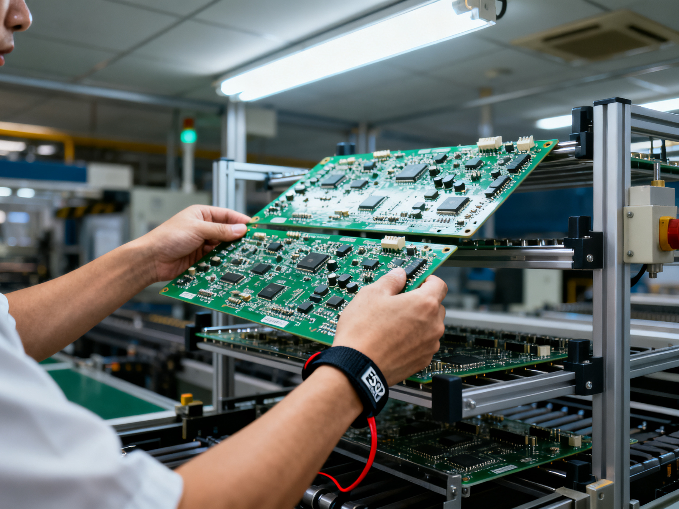
Common Defects and What Causes Them
Cold joints rank among the most frequent issues we see in production. The solder never fully melted, so it looks dull and grainy instead of shiny and smooth. Usually this traces back to the soak zone failing to bring everything to the same temperature before peak heat. You might also see this when thermocouples drift out of calibration.
Tombstoning shows up as components standing up on one end, like tiny tombstones. This happens when one pad heats faster than the other, pulling the component upright before the solder solidifies. Steep preheat ramps tend to cause this one.
Solder bridging creates unintended connections between pads. The solder flows where it shouldn’t and creates short circuits. This usually means too much paste was applied, or the reflow zone ran too hot, causing the solder to migrate.
Solder voiding leaves air pockets inside joints. These weaken the connection and can cause field failures. Voiding often comes from outgassing that wasn’t properly removed during preheat. We always recommend a longer preheat when dealing with large ground planes that trap air.
| Defect | Primary Cause | Quick Fix |
|——–|————–|———–|
| Cold Joint | Insufficient heat | Raise peak temp 5-10C |
| Tombstoning | Thermal imbalance | Slow preheat ramp |
| Bridging | Excess solder | Reduce paste volume |
| Voiding | Outgassing | Extend preheat time |
Prevention Strategies That Actually Work
First, build verification into your workflow. Run a thermal profiler on every new board design and after any equipment changes. Don’t assume a profile that worked for one board will work for another, even if they look similar.
Second, audit boards regularly. Pick a sample from each batch and inspect under magnification. Look for patterns. If you see the same defect on the same component location repeatedly, you’ve got a systematic problem, not random error.
Third, keep equipment maintained. Clogged nozzle conveyors cause board vibration that shifts components. Worn heating elements produce uneven heat. Fans that don’t spin properly create hot spots. Schedule preventive maintenance and stick to it.
Equipment Factors You Might Overlook
Thermocouple attachment quality matters more than most people realize. A thermocouple that’s slightly loose or positioned wrong gives bad data, which leads to bad profiles. Check your thermocouples monthly and replace them according to manufacturer schedules.
Conveyor belt tension affects how boards sit in the oven. A belt that’s too loose lets boards wobble, creating temperature variations as they travel through zones. A belt that’s too tight stresses the board edges.
Oven calibration drifts over time. Heating elements age, sensors degrade, and fans lose RPM. Most facilities schedule quarterly calibration checks, but high-volume operations might need monthly verification. The cost of calibration is tiny compared to the cost of a rejected batch.
Quality assurance in the smt reflow oven process isn’t a one-time setup. It’s continuous improvement based on real data from your production floor. Keep learning from your defects and your process will get tighter over time.
Best Practices for Double-Sided PCB Reflow
Double-sided PCB assembly adds a layer of complexity that trips up a lot of manufacturers. The core challenge? You’re essentially reflowing the same board twice, and the first pass affects everything that happens on the second pass.
When you reflow pcb in oven for the second side, you run the risk of disturbing components already soldered on the first side. The heat can melt those joints if you’re not careful, causing components to shift or, worse, fall off entirely. We’ve seen production batches come out with half the board looking perfect and the other half looking like a disaster. Not fun to explain to customers.
The most common approach is to populate and reflow one side first, then flip the board and repeat. But here’s what most people miss: the first side needs to be fully cured and cooled before you attempt the second side. Rushing this creates thermal shock that weakens joints or warps the board.
From Our Experience: Double-Sided PCB Challenges
We learned the hard way that adhesive matters just as much as temperature profiles. Without proper adhesive securing bottom-side components, gravity pulls parts down during the second reflow. Budget for high-temperature adhesive and apply it consistently.
Process modifications that help include using high-temperature adhesive to secure components on the bottom side before the second pass. You also want to dial back peak temperature slightly on the second run. Most profiles drop 5 to 10 degrees Celsius to protect the first-side joints from overheating.
For equipment, look for reflow ovens with zone isolation and precise temperature ramping. Modern double-sided reflow setups in 2026 often include closed-loop cooling on the bottom side to prevent heat migration upward. Some manufacturers use wave soldering for the second side instead, which avoids reheating the first side entirely.
The biggest wins come from careful board handling between passes. Minimize movement, store boards flat, and inspect under magnification before the second reflow. Catch problems early and you save yourself a world of rework pain later.## Future Trends and Recommendations in SMT Reflow Technology
So where does SMT reflow go from here? The technology keeps advancing, and staying ahead means paying attention to where the industry is heading in 2026 and beyond.
AI and automation lead the charge. Modern reflow ovens increasingly integrate artificial intelligence to adjust profiles in real time. Instead of running a static profile and hoping for the best, AI systems monitor board temperatures and tweak settings on the fly. This cuts defect rates and reduces the need for constant manual tweaking.
Miniaturization drives new requirements. Components keep shrinking. A 0201 component was tiny ten years ago, and now we’re dealing with 008004 packages that are barely visible to the naked eye. Reflow ovens need tighter temperature control and more precise heating zones to handle these delicate parts without damage.
Energy efficiency matters more every year. Manufacturing plants face pressure to reduce their carbon footprint. New reflow oven designs focus on better insulation, heat recovery systems, and shorter cycle times that use less power overall. The upfront cost might be higher, but the operational savings add up fast.
Industry 4.0 integration is now table stakes. If your reflow oven doesn’t connect to your MES or production tracking system, you’re behind the curve. Real-time data sharing lets you catch problems before they become costly defects.
For your shop floor, here’s what I’d recommend. First, audit your current profile against what you’re actually producing. Most facilities discover gaps they didn’t know existed. Second, invest in better thermocouple monitoring. Bad data kills good outcomes every time. Third, plan for upgrades. Budget for a new oven every seven to ten years, because older equipment simply can’t keep up with modern requirements.
The smt reflow oven process isn’t going away, but it will keep getting smarter. Companies that embrace these changes now will outperform those clinging to legacy setups.
Optimizing your smt reflow oven profile isn’t optional anymore. It’s what separates a competitive electronics assembly operation from one that’s always chasing defects and rework. Get it right, and your production line runs smoother, your customers are happier, and your bottom line shows the difference.