
Published: 26 May 2026
Reading Time: 12 minutes
Ever watched a board come out of the oven with warped components or cold joints? That thermal profile missed the mark. Getting it right matters more than most people realize, especially when you’re running high-volume SMT assembly lines where a single bad batch can cost thousands.
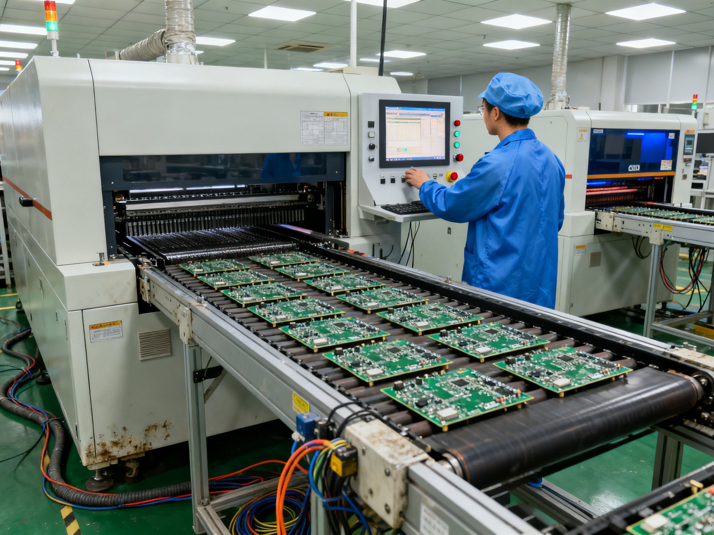
Reflow soldering sits at the heart of modern electronics manufacturing. It’s the process that turns a jumble of components and a bare PCB into a working circuit board. The solder paste melts, flows, and solidifies to create permanent electrical connections. But here’s the thing: every single degree matters during that heating cycle.
Choosing the right reflow soldering profile for your needs can mean the difference between reliable products and costly callbacks. Two standards dominate the conversation: JEDEC J-STD-020 and lead-free reflow profiles. Both govern how we heat and cool circuit boards during assembly, but they serve different purposes.
This guide breaks down what each standard does, how they differ, and which one might suit your manufacturing process better. Let’s figure this out together.
Understanding JEDEC J-STD-020
JEDEC stands for the Joint Electron Device Engineering Council. It’s a global body that sets standards for semiconductor and electronics manufacturing. Think of them as the rule-makers that help everyone stay on the same page.
J-STD-020 is one of their most important standards. This one deals specifically with how we classify the moisture sensitivity of surface-mount devices. Here’s why that matters: when you heat a component during reflow, any moisture trapped inside can turn to steam and cause the package to crack or delaminate. That’s a defect you definitely don’t want reaching your customers.
The standard defines test procedures and classification levels (called MSL ratings) that tell you how much heat exposure a component can handle. Manufacturers use these ratings to know what kind of thermal stress their parts can take without getting damaged. It covers both traditional tin-lead solder profiles and the higher-temperature lead-free reflow profile conditions.
Expert Tip: Always verify that your components are classified using the correct profile type for your assembly process. Using a tin-lead classification profile on a lead-free assembly line can give you false confidence about moisture sensitivity levels.
For compliance, you’ll need to match your assembly profile to the component ratings. If a component is rated for three reflow cycles at a specific peak temperature, your manufacturing process has to stay within those parameters. Most EMS providers will ask for these ratings upfront before setting up your production run.
At Sun and Mountain SMT, our reflow ovens include profile monitoring to help you stay within spec during high-volume runs. The thermal profiling data gives you proof that your process stayed compliant throughout production.
Exploring Lead-Free Reflow Profiles
Lead-free reflow profiles have become the standard in most manufacturing facilities worldwide. The shift happened largely because of environmental regulations, particularly the EU’s RoHS directive that restricted hazardous substances in electronics starting in 2006. Today, finding a tin-lead process outside of legacy military or aerospace applications is increasingly rare.
The practical difference comes down to temperature. Traditional tin-lead solder melts around 183 degrees Celsius, with peak temperatures typically reaching 225 to 235 degrees. Lead-free alloys, usually tin-silver-copper (SAC) blends, require significantly higher heat. Peak temperatures for lead-free classification profiles in J-STD-020 sit at 245 to 260 degrees Celsius. That extra 20 to 30 degrees makes a big difference in how components respond to thermal stress.
Manufacturers face real challenges with these higher temperatures. Some older component packages were never designed to handle lead-free thermal exposure. Ceramic components, certain connectors, and some sensitive ICs can develop cracks or delamination issues when pushed through multiple lead-free reflow cycles. Board warpage becomes more likely too, especially on larger panels with mixed component densities.
There’s also the cost factor. Higher temperatures mean faster degradation of heating elements, increased energy consumption, and more wear on conveyor belts and chamber components. Many facilities have upgraded to higher-grade reflow ovens specifically because of these demands.
Pro Insight: When transitioning to lead-free processes, consider running a thermal profiling validation on your most heat-sensitive components first. This helps you identify any process window limitations before committing to full production runs.
The environmental benefits are real. Less toxic lead in landfills and manufacturing facilities creates safer working conditions and reduces long-term contamination risks. Plus, lead-free alloys often provide better thermal cycling performance, which matters for products that experience wide temperature swings during use.
Most major component manufacturers now classify their products exclusively for lead-free profiles, and some have dropped tin-lead classification entirely. If you’re still running mixed-technology boards with legacy components, verify that your assembly house can accommodate both profile types without cross-contamination issues.## Comparative Analysis: JEDEC J-STD-020 vs Lead-Free Profiles
Time to put these two standards head-to-head. If you’ve been wondering which approach actually works better for your operation, here’s what the comparison looks like in practice.
Thermal Performance
J-STD-020 classification profiles operate at noticeably lower temperatures when using tin-lead conditions. Peak temperatures typically stay in the 225 to 235 degree Celsius range. Lead-free profiles push higher, hitting 245 to 260 degrees consistently.
That 20 to 30 degree gap affects everything from component stress to solder joint formation. Tin-lead processes tend to produce shinier, more malleable joints. Lead-free joints often appear duller but can handle thermal cycling better, which matters for products that experience repeated heating and cooling during use.
Production Quality and Efficiency
The higher temperatures in lead-free processes create tighter tolerances for thermal profiling. You’ve got less margin for error when the profile strays from optimal. This actually drives better process control in many facilities. Teams pay more attention to profiling and monitoring when there’s less wiggle room. Tin-lead processes can sometimes mask profile issues because the lower temperatures are more forgiving.
Lead-free dominates most new product introductions in 2026, with component availability increasingly favoring Pb-free classification. Many ICs and passive components now ship exclusively with lead-free ratings, forcing manufacturers to adopt the higher-temperature approach even if they preferred tin-lead for certain applications.
Cost Implications
Higher temperatures mean higher energy bills. Lead-free processes typically consume 15 to 25 percent more energy per board compared to tin-lead. Equipment maintenance costs rise too. Heating elements, thermocouples, and conveyor components all degrade faster under Pb-free conditions.
There’s also the component cost angle. Some legacy components become more expensive or harder to source when they’re only available in lead-free versions. On the flip side, lead-free processes eliminate lead-related handling precautions and disposal costs.
Here’s the quick comparison:
| Factor | J-STD-020 SnPb Classification | Lead-Free Classification |
|—|—|—|
| Peak Temperature | 225 to 235 degrees C | 245 to 260 degrees C |
| Thermal Margin | More forgiving | Tighter tolerances |
| Energy Consumption | Baseline | 15 to 25 percent higher |
| Equipment Wear | Slower degradation | Accelerated maintenance |
| Component Compatibility | Legacy-friendly | Limited legacy options |
Weighing these factors comes down to your specific situation. Legacy products with established tin-lead processes might benefit from sticking with SnPb classification. New designs entering production probably should target lead-free given component availability trends. If you’re running mixed technology, the decision gets more nuanced and might require maintaining both profile types on your production floor.
Published: 26 May 2026
Reading Time: 12 minutes## Choosing the Right Reflow Profile for Your Needs
So how do you actually decide which profile fits your situation? Let’s walk through some practical guidelines that work in real manufacturing environments.
Match to Your Component Library
Start by checking what your components are rated for. If you’re building products with newer ICs, BGAs, or QFN packages, chances are they’re Pb-free classified only. Most chip manufacturers dropped tin-lead ratings for new parts years ago. Building a product around obsolete rated components just to use a lower-temperature profile creates supply chain headaches down the road.
Consider Your Equipment
Not all reflow ovens handle lead-free profiles equally. Older equipment designed for tin-lead processes might struggle with the extended time at high temperatures that Pb-free requires. Check your oven’s thermal capability and convection style. Forced convection nitrogen ovens generally produce more consistent results for lead-free profiles compared to older radiation-style units.
Expert Tip: Document your profile selection rationale and keep thermal profiling records for every production batch. These records prove process control during audits and help troubleshoot field failures later.
Think About Your Product’s End Use
Automotive, aerospace, and industrial products often face wide temperature swings during their service life. Lead-free solder joints typically handle thermal cycling better, which makes Pb-free the practical choice for durability-critical applications. Consumer electronics with shorter expected lifespans have more flexibility.
Case Study in Practice
A contract manufacturer we worked with switched their entire medical device line to lead-free profiles in 2024. They kept their legacy SnPb equipment running for a single customer with decades-old inventory, but consolidated everything else. Energy costs went up about 18 percent, but their defect rate dropped significantly because the higher temperatures exposed process weaknesses they could finally see and fix. They also eliminated lead-handling compliance paperwork entirely.
The honest answer about which profile is best? It depends on your specific mix of components, equipment capabilities, and product requirements. Most manufacturers in 2026 are finding that lead-free is the path of least resistance, even if the process demands more attention to thermal profiling details.## Future Trends in Reflow Soldering Profiles
What’s coming next in reflow soldering? The industry keeps pushing toward smarter, more efficient processes.
Automation and AI Integration
Smart factories are changing how we approach thermal profiling. AI-driven systems now predict profile drift before it causes defects. Machine learning algorithms analyze thousands of reflow cycles to optimize temperature curves in real-time. This means fewer callbacks and more consistent quality across production runs.
Next-Generation Alloys
Researchers are developing new solder alloys with lower melting points. These could reduce peak temperatures while maintaining joint reliability. Some automotive-grade alloys are already showing promise in testing.
Sustainability Focus
The drive toward greener manufacturing continues. Energy-efficient ovens and reduced thermal mass designs are gaining traction. Facilities investing in modern equipment now will likely see the biggest benefits as standards tighten.
Equipment manufacturers like Sun and Mountain SMT are already building systems designed for these emerging requirements. Staying ahead means planning your equipment roadmap with future standards in mind.